Theoretically, I can't see a problem if the twisted pair has an end of cable termination that is: -
- A single resistor (R) that matches the characteristic impedance of the cable placed across the two ends of the pair or,
- Two resistors (\$\dfrac{R}{2}\$) across the two ends of the pair with the centre-point tied also to the shield/screen.
Practically, when looking through data sheets I tend to see option 2 more than option 1.
Today, I had to use option 2 because option 1 caused a noticeable time lag (about 2 or 3ns) between the two conductors over 50m of cable. This surprised me and I'm wondering why this should be so. The signal I was driving at one end was about 2V logic levels and very balanced in nature (no discernible time difference or noticeable amplitude difference).
Question - why should option 2 be better than option 1 in the set-up I've described and is it possible that there is something theoretically better about option 2?
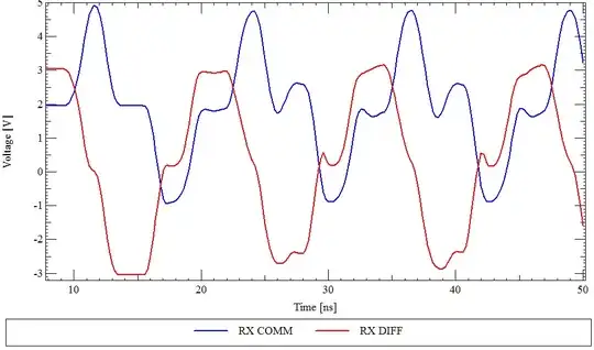 Scheme #1 with only differential mode termination.
 Scheme #2 with both differential and common mode termination.