6

I have two LVDS differential pairs on my PCB, running from a connector. On the connector, I have the following sequence of nets:

  • GND
  • LVDS+
  • LVDS-
  • GND
  • LVDS+
  • LVDS-
  • GND

This is as I have seen suggested:

LVDS ribbon cable

So the GNDs pins are very close to the LVDS pins. However, advice I have seen regarding LVDS PCB layouts suggests that I should keep some clearance between the LVDS tracks and anything else, including the GND plane. This seem to be conflicting advice.

What's the best way to lay out the LVDS tracks running from my connector?

Ground plane close to differential pair LVDS lines

Continue the GND plane close to the track as it is on the connector? Or leave clearance and risk an impedance change?


Added: There is also an unbroken ground plane underneath the differential pairs.

Rocketmagnet
  • 26,933
  • 17
  • 92
  • 177
  • 1
    Do you have a link for the advice you read regarding LVDS clearance to gnd? – Andy aka Nov 11 '13 at 12:33
  • @Andyaka - Hmm, perhaps I confused myself. The advice seems to say keep a clearance between LVDS-TTL, or LVDS-LVDS, but doesn't explicitly say LVDS-GND. – Rocketmagnet Nov 11 '13 at 12:51
  • @Rocketmagnet Advice you don't really understand is often just that: Confusing... :-/ – Rolf Ostergaard Nov 11 '13 at 12:55
  • @Rocketmagnet If the images are a real layout - just looking at the geometries it looks like you would benefit from moving the GND plane closer to the signal layer. That will make the traces skinnier (keep 50R) and allow more spacing. And your signal layer fill will turn into a nice looking "feel-good-fill" if you just keep it far enough away :-). – Rolf Ostergaard Nov 12 '13 at 14:38
  • @RolfOstergaard - Thanks. Well, I've sent off for a prototype of this board, so I'll see how it behaves on EMI. If it's good enough as it is, I'll leave it. – Rocketmagnet Nov 13 '13 at 20:20
  • I thought you we asking a signal-integrity question and not an EMI question????? – Rolf Ostergaard Nov 16 '13 at 10:23
  • @RolfOstergaard - Sorry. I realise now that I didn't make that clear. Yes, I'm mainly concerned with EMI, but also with SI. However, it's easier for me to test EMI because I can take it to the chamber. However, I don't have a good enough scope to take an eye diagram, so I can't really see what effect I've had on SI. – Rocketmagnet Nov 16 '13 at 17:19

2 Answers2

4

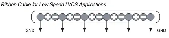
If you remember that a differential signal is really just two single-ended signals that happen to have signals that change in the opposite direction at the same time, it's fairly simple to see what to do.

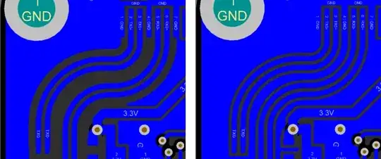
1) Make sure you have half the differential impedance between the individual traces and the reference plane below. For LVDS that would be 50R trace impedance. Notice that distance to the other trace in the pair as well as other Cu will impact the impedance. Use a 2D field solver to do this (The best free tool I have found is TNT).

2) Make sure you don't have too much crosstalk between any traces (this includes crosstalk between the two traces of that pair, although this is often not much of an issue - see note below).

Yes this may be contradictory advice to what you may read in some app notes, but do your own research in books like the two excellent books on signal integrity by Lee Ritchey (you can legally get the first one "Right the First Time, volume I" as a free or cheap download on the net).

Note on #2: You will (obviously) also have crosstalk between the two traces of the pair. And at just the point where the signals switch (both signals switch at the same time). The end result of that is a degradation of the edge rate.

Now if you follow advice #1 you will have more than plenty spacing between the two traces that this will normally not be a problem for your circuit. Actually most often analysis show that this is not a likely issue. It is just mentioned here for completeness.

Does this help you? I will be happy to expand the answer.

Rolf Ostergaard
  • 4,448
  • 18
  • 24
0

In number 2, you risk converting any pair close to the surface plane into a coplanar waveguide (which will change the effective impedance of the pair).

See this answer for more details.

Peter Smith
  • 21,923
  • 1
  • 29
  • 64