2

Here is the setup I use.

enter image description here

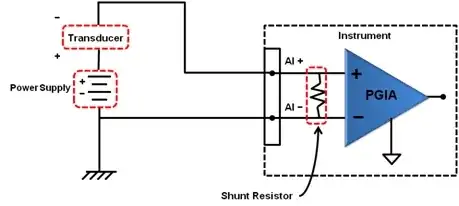
Since the DAQ system is only able to read voltages first I record the voltages by a shunt resistor. But I need the "current values" at the end. Transducer will make the current vary between 4 to 20 mA.

If the resistance is constant with respect to current one could just divide the voltage readings to resistance and obtain the current in the loop.

But I observed that the resistance is not the same for different currents. For example for a constant applied 20mA current the resistance is 248.74ohm and for 4 mA 248.27ohm. Is it better in that case to obtain a calibration expression (current to voltage) and calculate the currents in that way instead of taking the resistance a constant?

Kevin Reid
  • 7,444
  • 1
  • 25
  • 44
user16307
  • 11,802
  • 51
  • 173
  • 312
  • How sensitive is your measurement to these errors? What are your other system errors? You're talking about a 0.2% error between 4 and 20mA - that is already extremely good for an uncalibrated system. – user36129 Nov 11 '13 at 10:50
  • i obtain a current voltage line. my question is should i use this line to calculate the currents from voltage readings or should i choose a constant resistance value? which is more accurate? – user16307 Nov 11 '13 at 10:57

1 Answers1

1

At 20 mA the resistor will be dissipating more power than at 4 mA. Say the resistor is 250 ohm (as per your previous question How to achieve common ground for a single ended input?), the power will be 100 mW at 20mA whereas at 4 mA the power will only be 4 mW.

If your resistor warms up 10 ºC and is a 25ppm/ºC type the resistance change will be from 250 ohm to 250.06 ohms or down to 249.94 ohms.

If your resistor warms up 20 ºC and it is a 50ppm/ºC type the resistance will change from 250 ohm to 250.25 ohms or down to 249.75 ohms.

This seems around the same order as what you are measuring. I calculate a change in resistance of 0.47 ohms - could this be due to self-heating?

Andy aka
  • 434,556
  • 28
  • 351
  • 777
  • I obtain that line(current input - voltage output) with 2 measurements i.e. for 4mA and 20mA constant current. I obtain a line because I dont have another measurement point. My constant current source outputs only 4 and 20mA. I obtain the calibration expression (current-voltage) as linear but Im not sure it should be linear in real since I can only measure at 2 steps. – user16307 Nov 11 '13 at 11:29
  • Precisely what is the make and model of your resistor - let's get to the heart of the problem. Did yesterday's advice on the previous question help? – Andy aka Nov 11 '13 at 11:32
  • the point is the resistor has no color code. it is totally black. i have no data sheet. thats why i try this method. some engineer before be measured it as 249.5 something 2 years ago. but they want me to use this resistance. so thats why im measuring again – user16307 Nov 11 '13 at 11:37
  • The error you get is likely to be this - without a spec you are in the dark. Get a resistor like this one: http://uk.farnell.com/vishay-foil-resistors-vpg/1625250r000t9r/resistor-precision-250r-1206/dp/1109038 it is 0.01% and has a temperature coefficient of 0.2ppm per ºC or maybe something a bit less expensive. The error you are getting can easily be down to the resistor or maybe the offset voltage drift of your amplifier. Did the info I gave yesterday help? If so please consider accepting the answer or upvoting it. This site favours those who show some form of appreciation for useful advice. – Andy aka Nov 11 '13 at 11:47
  • it didnt help much because im not getting clear answers to my questions. i have to use this resistor. thanks for ideas anyway. my question was is that better to calibrate versus current or take resistance as a constant. im asking which is more accurate. i cant change the setup unforunately not in my control – user16307 Nov 11 '13 at 11:55