1

enter image description here

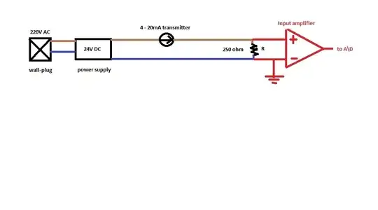
I'm using a current loop transducer as in the set up picture I provided. The transmitter is regulating the current proportional to a physical quantity and regulating the current. It is a typical 4 to 20 mA loop. We have a data acq. board which can read voltages so we read the voltage from 250 ohm resistor's ends. We use single ended input(red colored in my picture). Input amplifier is part of the data acquisition board. From R we use a BNC cable to connect to the DAQ board.

But in this link: http://www.ni.com/white-paper/7113/en/ (look at Figure 5) my setup seems to be not recommended. Isn't my setup common grounded?

Null
  • 7,448
  • 17
  • 36
  • 48
user16307
  • 11,802
  • 51
  • 173
  • 312

2 Answers2

2

Figure 5 is really saying that having two grounds on the system can cause problems. Those that do have two seperate grounds are fed into differential amplifiers which effectively circumvent the problem of multiple grounds.

Figure 5 has two columns and the diagram that has the cross through it is in the column marked "ground referenced signal sources". If your measurement device has galvanically isolated signals from it's metal casing (if it has a metal case) then there should be no problem - it falls under the column marked "floating signal sources".

Andy aka
  • 434,556
  • 28
  • 351
  • 777
  • the daq box is also connected to a wall plug. i think all plugs' grounds connected internally in a building. i still cannot see the difference between Figure 5 and my setup where also grounds are connected to each other and separately grounds:( – user16307 Nov 09 '13 at 22:26
  • @user16307 - "If your measurement device has galvanically isolated signals from it's metal casing (if it has a metal case) then there should be no problem" - the current passing thru the 250 ohm resistor is totally controlled by the device. – Andy aka Nov 09 '13 at 22:31
  • http://www.dataq.com/support/documentation/pdf/article_pdfs/process_current2.pdf Here it says in Figure 2 better to measure the potential differences between two grounds even though they are connected. is that to be sure if their ground same internally? – user16307 Nov 10 '13 at 00:26
  • No you are misinterpreting what figure 2 is about and this does not apply to your circuit. Fig 2 is about using an instrumentation type amplifier to measure a ground referenced signal where noise might exist between the two grounds and could cause the amplifiers inputs to be taken beyond it's power rails. – Andy aka Nov 10 '13 at 08:05
  • ok sorry but last question to be sure if i understood. here is what i understand: so my power supply and the data acquisition equipment they both have floating grounds and they are connected to each other establishing a common ground. but these grounds (or common ground) has no connection with the neutral line or earthing of the inline house electric network. they are both totally isolated. but the figrure 2 in the link the grounds are grounded to the house network's ground.. is that right now what im saying? thnx. – user16307 Nov 10 '13 at 12:16
  • and if it is right if so i should delete the ground (red color) in my picture because it was my wrong assumption that it was connected to the house network ground ? – user16307 Nov 10 '13 at 12:18
  • Your circuit in your question is a perfectly valid way of measuring. A better input circuit using an instrumentation amplifier still needs a ground but that could be through a high impedance maybe 10k or greater and would prevent earth fault currents between power supply and measurement circuit. Neutral has nothing to do with anything. – Andy aka Nov 10 '13 at 13:45
0

You are correct in that, for this circuit layout, you want only one end of the circuit grounded.

Do a continuity test between the earth pin of your transmitter power supply and the DC output terminals. You'll probably find that there is no connection and that the DC is 'floating' with respect to ground, in which case you're fine. The earth, if used would usually only be connected to the metal case to protect the user in case of internal fault.

Transistor
  • 168,990
  • 12
  • 186
  • 385