10

I am planning to build a series of Arduino-controlled temperature-reporting units for a room full of "Ultracold" -80°C freezers. (I ultimately want to convert the signal to a serial stream that will interface with my existing system.)

So far I have only found one-wire and other sensors that are only rated to -55C. In my application they would spend most of their time around -80C. I only need about 0.5 to 1 degree accuracy at those temperatures.

Does anyone know a source for a low-temperature sensor that would be arduino-compatible, reliable, and be able to be placed at the end of a wire (to be passed into the freezer through a small port)?

Small update below.

beroe
  • 201
  • 2
  • 7
  • Hey, were you able to get started on your project? I'm also interested in something similar, but I don't quite understand how it's supposed to work. Does the Arduino go inside the freezer or do you dangle just the probe inside, through the rubber seal? Wouldn't that create an air leak? – Superbest May 20 '14 at 17:21
  • I am out on a ship right now, so can't give you the full details, but we are going to try a thermocouple from Adafruit, if I recall. The Arduino will be outside and the wire will snake in. Should seal OK and I think most freezers come with a little sensor port as well. I will update once we have some results, but the engineers that are helping got busy on their real jobs... – beroe May 21 '14 at 08:19

6 Answers6

11

The forward voltage (\$V_f\$) of a diode at a small constant current is often used to measure low (cryogenic) temperatures. Silicon diodes have a \$V_f\$ which is nearly a linear function of temperature over a wide range, with slope approximately -2 mV/K. There are even specially-built diodes standardized to specific \$V_f\$ vs. T curves. If you're willing to do a two or three point calibration yourself, then you can use an ordinary signal diode. Even a 1N4148 can accurately measure liquid nitrogen temperatures if you calibrate it.

You can improve accuracy by:

  • using a stable constant current supply
  • using separate pairs of wires to supply current and measure the voltage
  • using shielded twisted pair cabling
  • applying an appropriate scale and offset to the measured voltage before feeding it to the ADC
Theran
  • 3,432
  • 1
  • 19
  • 21
  • 3
    This technique works very well. I once built a system that measured the temperature of N2 gas coming off a closed cryogenic container that contained liquid nitrogen. The container also had an ~500W heater core inside that was used to boil the liquid and create a gas pressure at the top that allowed the cold gas to escape into a out flow pipe. The pipe was Teflon tubing to prevent warming the gas too much before it was delivered to the point of use. I used 1N4148 diodes biased at 1mA to measure the gas temperature at the delivery point. The temperatures were in the -150C range at that point. – Michael Karas Nov 07 '13 at 22:48
  • 2
    An example of a specialized extended range (1.5K to 500K) temperature measuring diode can be seen here: http://www.omega.com/pptst/cy670.html. But those, of course, are very expensive, hundreds of dollars each. – oakad Nov 08 '13 at 00:59
  • This is really interesting! I wonder if I am up to the challenge... – beroe Nov 08 '13 at 01:53
10

A type T thermocouple work well down to ~-200C. To make life a little easier the thermocouple can be interfaced with an AD595 or similar chip which provides cold junction compensation and amplifies the voltage output. However, care needs to be taken with a Type T thermocouple as these devices are primarily made for Type K. The data sheet lists some special considerations for use with Type T. The output from the AD595 could then be read in with the AD of your arduino and scaled appropriately.

enter image description here

Mark
  • 732
  • 1
  • 8
  • 17
6

We use lots of plain-old SR106 Schottky diodes to measure liquid helium temperatures (4K-20K) where I work. They are great, and cheap as hell.

You need a constant current source (we use 10 or 100 uA, mostly to reduce heating and boiloff), and you really, really should use 4-wire connections, but all you really need for the electronics are the diode, and op-amp for the current source, an instrumentation amp for reading the voltage back, and a handful of passives.

The tricky bit is the calibration, but assuming you have a temperature meter that works at those temperature, you can just use that as a transfer standard.

We actually have a few of the fancypants, expensive cryo-specific diodes like @ user16653 mentioned in the comments to @Theran's answer, and they really aren't distinguisable from the cheap, homemade sensors which is just a SR106 epoxied into a little copper block, to make it easy to thermally strap to the device under test.
The primary advantage of the commercial cryo diode sensors is they are calibrated, but if you have one that's calibrated, you can just use it as a transfer standard to calibrate all your other homemade sensors pretty easily, and at that point, they all work about the same.


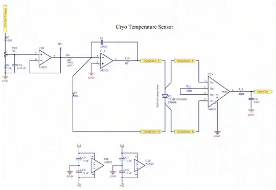
This circuit is a precision current source for driving a diode in a cryogenic system.

Basically, there is a -10V precision reference (not shown. Note that the reference is negative) that comes in on the right. It's divided down in VR1, and buffered through U1B.

Now, U1A will strive to keep the voltage at it's inputs equal, since we have the output connected back to the negative input (through the diode).
This means that the voltage at pin 2 of the U1 will be maintained very, very close to 0V. However, no* current can flow in or out of the op-amp input (they're high impedance), and no current can flow through C1, so basically the only path for current to flow into the negative summing node of op-amp U1A is through the diode.

Therefore, the current flowing through R6 is equal** to the current flowing through the diode. Since we know the voltage at the pin (functionally it's 0V), we can easily calculate the diode current, since we know the voltage at TPC, and the resistance of R6.

C1 reduces the loop bandwidth, to keep the circuit stable. You could experimentally reduce it's value until the circuit oscillates, if you need lots of bandwith, but that seems unlikely for a thermal application.

R10 is just there to protect the op-amp in the event of something stupid happening, like the output leads getting shorted.

enter image description here

Note that you need a fairly decent negative voltage reference, as drift in your negative voltage reference will directly result in drift in your bias current, causing incorrect measurements.

You should also use a decently low tempco resistor for R6 (metal film at the minimum).

In real-world applications, I just stuck a precision ammeter in place of D1, and tuned the pot to get the current I wanted, rather then bothering calculating it out from the math, but either approach would work.

You should also use a decent, low offset & low bias current op-amp. Analog devices makes lots of nice parts.

* technically, a extremely small current flows in or out of the inputs of all real-world op-amps. If you're using a modern, low-bias-current op-amp, it's small enough that we're ignoring it here.

** see above note about op-amp input bias currents.

Connor Wolf
  • 31,938
  • 6
  • 77
  • 137
  • Great info. Thanks for all the details. I will run these all past some engineer friends to see what we are most equipped to pull off. – beroe Nov 08 '13 at 17:22
3

The conventional way to measure very low or very high temperatures is to use thermocouples. These can be run remote a reasonable distance from the location where the thermocouple interface is located.

You would have to provide for the conditioning circuitry needed to convert the voltage on the wires into a format that can be accommodated by the Arduino. One way you could try out this approach is to use the thermocouple breakout board from Adafruit. This small board could connect to the Arduio via a SPI connection to the on board control chip. To support many of these boards you could select the board to talk to on the SPI using some external shift registers to support select of a larger number.

Michael Karas
  • 56,889
  • 3
  • 70
  • 138
2

One option that you may want to consider, if the use of temperature sensing diodes or the Vbe junction of a low cost NPN transistor looks attractive to you, is to look at a chip such as the ADT7476 from On Semiconductor. This device allows the connection of two remote diode sensors and converts temperature value into digital values in internal registers. The register reading range from the data sheet seems that if could extend down to be in the range of interest for you provided the IC package is not that cold.

The part presents a convenient I2C interface on the Bus side.

These parts are fairly reasonably priced and can be purchased from Mouser Electronics.

If you decided to try out this approach I would recommend that you put the remote diodes in the freezer and connect with 2-wire twisted pair through GND connected foil shielded cable. The cables would connect back over to a piece of warm room electronics that you would have to build that included what ever number of the ADT7476's you needed and the connections for the Arduino to attach to.

Michael Karas
  • 56,889
  • 3
  • 70
  • 138
0

UPDATE: We have been running with this K-type thermocouple, although it is not the optimal range. We tried a J-type, which is supposed to work at those temperatures better, but could not get the amplifier board to give the proper calibration. Still a back-burnered project. We might also want to find a paired T-type as @Mark recommended.

I tried potting the thermocouple with Sugru and embedding a magnet for securing it inside the fridge. This worked pretty well and gave some thermal inertia to the sensor.

Over long-term in our testing, the braided thermocouple got moisture damage and the sleeve wore away. Also it did seem to create some leakage and condensation to come past the door seal, so we will have to find a pass-through port.

beroe
  • 201
  • 2
  • 7
  • This isn't an answer (as you have indicated on the first line). It belongs in the original question. Remember that answers float up and down by votes and user sorting preference - unlike a forum. Please paste the information into your question and delete this. – Transistor Sep 26 '17 at 20:43
  • I was putting it in as an edit to question, but then thought that listing the thermocouple we have been using and the amp board qualified it as an answer... – beroe Sep 26 '17 at 21:03
  • Oh, OK. If you're happy with your solution that's fine. You can even accept it as the correct answer. Chuck a few votes to the guys who did good work ... – Transistor Sep 26 '17 at 21:14