8

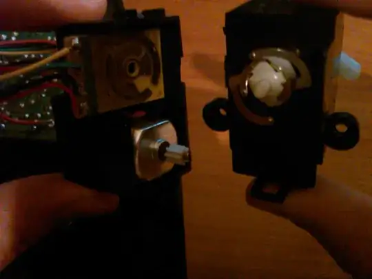
I want to use a servo taken by a radio-controlled car. However, I found out that wheels' rotation (front wheels) is not performed by a servo, but from a motor to move the wheels and a mechanism for control, into a steering box.

Specifically, there are 2 wires (red/black) that connect controller board with a motor. Motor communicates with a set of gears.

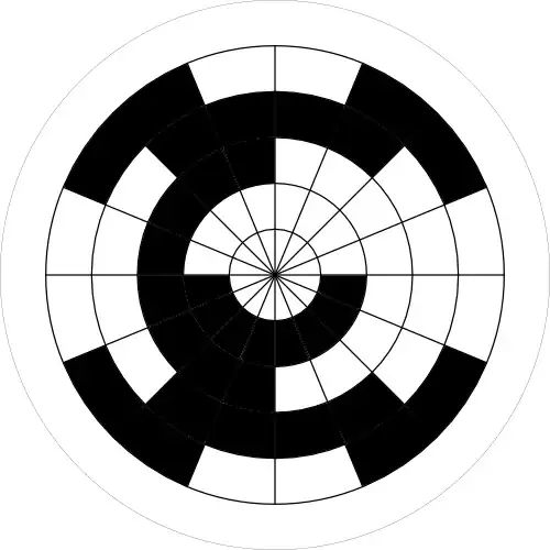
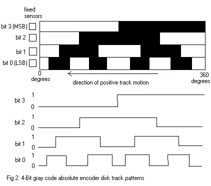
Control (this is the part I can't figure out) is performed by 4 wires, that end up to a simple circuit. Depending on which wire transfers electrical current, it's conductive area has current too. Set of gears that motor communicates with, connects to this circuit with 4 metallic cyclic endpoints.

Does anyone know how exactly control is performed? Is important to decode the operating mode, as I intend to use mechanism for another implementation.

enter image description here enter image description here

Samuel
  • 11,811
  • 31
  • 51
dempap
  • 649
  • 1
  • 11
  • 22

2 Answers2

10

Looks like a gray code rotary encoder. There is a nice tutorial here of a two output version. Good to wrap your head around.

You've got four outputs, so it's a four bit gray encoder. There are some truth tables of those outputs here and shown below.

But, now that you know what you're looking for you'll find a plethora of information. It'll make your head spin...

enter image description here enter image description here

Samuel
  • 11,811
  • 31
  • 51
  • I 'm trying to figure out the way motor and control mechanism communicate. If I 'm correct, each time I send a signal for control, I apply power to motor too, which power has effect until the 4-bit condition isn't true. – dempap Nov 07 '13 at 09:34
  • I think supply pins are those that end up to the motor. Motor communicates with the 4 metallic cyclic endpoints through a set of gears (if motor spins, these 4 spikes spin and consequently servo horn also. I admit I can't understand how motor and control interconnect. Let's assume I want to rotate horn. I have to power on the motor and send the appropriate signal, through the 4 wires, am I write? (new image has been added) – dempap Nov 07 '13 at 20:46
  • @dempap Not quite. The motor is powered separately, and will spin as long as you tell it to. The four wires are there to detect the location of the servo horn. Because this is a four bit encoder you have 16 positions you can detect (4^2). Check the diagram above, it decodes the output values from the four wires into a position in the range of rotation, for the diagram, that's 360 degrees. Measure the values, then check the diagram, there is only one spot out of the 16 that matches that combination; now you know where the servo is positioned. – Samuel Nov 07 '13 at 22:24
  • With this in mind, the 4 wires are working as a type of feedback. I can't send a signal through them, I just receive via their output values, the servo horn position. – dempap Nov 08 '13 at 14:04
  • @dempap That is correct. – Samuel Nov 08 '13 at 17:58
0

I'm playing with one of these too.

2 wires for the DC motor. Reverse polarity to change direction.

4 wires for the encoder, giving you 5x unique positions.

  1. Far left (A connected to D and B connected to C)
  2. Left (A connected to D)
  3. Middle (no connections)
  4. Right (B connected to D)
  5. Far right (B connected to D and A connected to C)

encoder

I came up with this method for reading the position. There is probably a more efficient method, but this worked for me.

  1. Connect A,B,C,D to digital pins.
  2. Setup A,B as input with pull-down (so they read LOW when floating).
  3. Setup C,D as output.
  4. loop()
  5. Set C=LOW and D=HIGH
  6. Read A and B (as A1,B1)
  7. Set C=HIGH and D=LOW
  8. Read A and B (as A2,B2)
A1    A2    B1    B2    Position
HIGH  LOW   LOW   HIGH  1 Far left
HIGH  LOW   LOW   LOW   2 Left
LOW   LOW   LOW   LOW   3 Middle
LOW   LOW   HIGH  LOW   4 Right
LOW   HIGH  HIGH  LOW   5 Far right

To use this motor for steering my RC car, I am using a mini L298N H-bridge module. DC in for the motor and IN1 and IN2 to control speed and direction.

Use PWM to adjust DC motor speed and brake once at positions 1, 3 or 5.

IN1   IN2   Mode
PWM   LOW   Rotate left / backwards
LOW   PWM   Rotate right / forwards
LOW   LOW   Off
HIGH  HIGH  Brake
Mike Causer
  • 135
  • 7