2

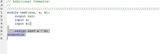
I am very new to FPGA and sorry for this elementary question. I just made a very simple XOR code like this with Webpack ISE to download to XC2S100 ( just for test!) but it does not work.

EDITION1: According to comments, I checked DONE situation after programming and it is in High state. Also added pull down resistors to a and b. Also added a 1KΩ pull down resistor to TMS. Now it works fine but after I restart the device, it does not work any more.It seems the configuration memory is erased after shut down.

enter image description here

1- Obviously this code sythesizes well, and simulation is OK. Then Implemented -> Assigned pins -> re-implemented -> and finally Generated .bit file ( this sequence: )

enter image description here

2- I also used the pins that don't require Vref. ( a:P3 , b:P4, out:P7). Here is a screenshot of pin assignment. At the end clicked Save:

enter image description here

3- Then I re-implemented and checked the pins in design summary. All OK:enter image description here

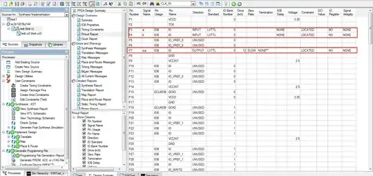
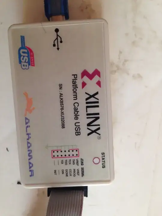
4- I have one of these Alkamar download cables. I connected the pins as recommended and ran iMPACT . It finds the device well and reads its config also well. I was happy when I saw "Program Succeeded " message! but when I connect VCCO voltage (3.3v) to P3(a) or P4(b), nothing happens in P7(out).I double checked everything but of no avail!

What is going wrong there?

enter image description here

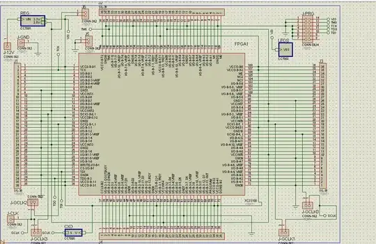
Here is the schematic I use:

1- Test board:

enter image description here

2- Power Supply:

enter image description here

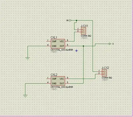
3- Crystal Oscillator part ( Not used in this test ):

enter image description here

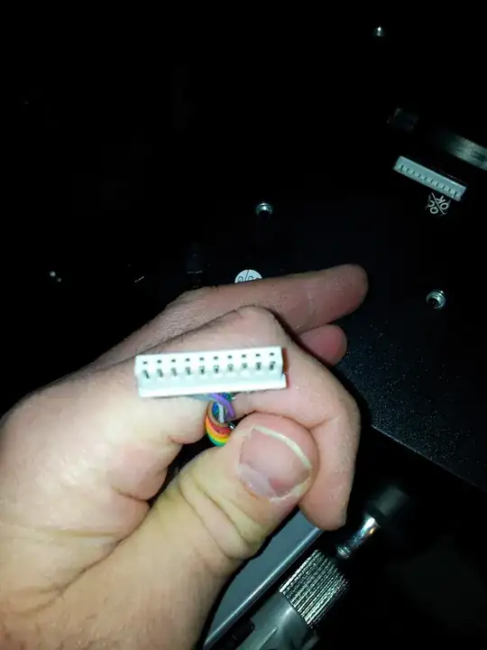
This is the programming cable:

enter image description here

Aug
  • 1,561
  • 6
  • 28
  • 63
  • Is there anything to pull the pins low on your board? (pull down resistors, manual pull down with wires, etc.) – alex.forencich Nov 05 '13 at 15:46
  • @alex.forencich No. Should I have them for XOR gate? – Aug Nov 05 '13 at 15:47
  • Is it correct, you didn't connect Vcco until after you programmed the part? That is not a good procedure. You should apply all of the Vcc's. Then program the part. – The Photon Nov 05 '13 at 16:10
  • @ThePhoton . No I connected all VCCOs and VCCINTs BEFORE programming. without that iMPACT shows an error : "Cable Not Found" – Aug Nov 05 '13 at 16:14
  • When you connected Vcc to P3, what did you connect to P4? – The Photon Nov 05 '13 at 16:18
  • @ThePhoton it is connected to nothing! Should I ground it or connect to VCCO? – Aug Nov 05 '13 at 16:20
  • Try both. You should see opposite signals on the output. Another question --- did you check for the DONE pin going high (IIRC) after programming? I'm not 100% sure if Impact checks for this before declaring success. – The Photon Nov 05 '13 at 16:21
  • @ThePhoton I added a photo of the programmer. I use JTAG and it is not connected to DONE. Can it be source of error? – Aug Nov 05 '13 at 16:25
  • You can use a DMM to check the DONE pin. If it is not coming high (again, IIRC) then it means the device is stuck for some reason between loading the program and starting to run. – The Photon Nov 05 '13 at 16:27
  • 1
    You should probably have pull-ups/downs on M0, M1, M2, PROGRAM, INIT, CCLK, TMS, and TCK (and maybe some I forgot) to make sure the device doesn't re-enter programming mode when it should be running normally. – The Photon Nov 05 '13 at 16:29
  • @ThePhoton one other question: As this is a simple XOR, I have not made a Timing constraint. Do I need it for such static design? – Aug Nov 05 '13 at 16:31
  • DONE itself might need a pull-up. Check all this out in the Configuration Guide --- I'm giving it to you from memory and I haven't done an FPGA design in more than a year. – The Photon Nov 05 '13 at 16:31
  • @Aug, timing constraints won't have any effect in this design. – The Photon Nov 05 '13 at 16:32
  • Try adding a pull-up resistor to the DONE pin and pull down resistors to both of the XOR gate inputs and try it again. – alex.forencich Nov 05 '13 at 16:47
  • @alex.forencich Can I use internal pullup/downs? I am newbie and couldn't find where to set internal pullup/downs. – Aug Nov 05 '13 at 16:54
  • Try it with physical resistors first. – alex.forencich Nov 05 '13 at 16:55
  • See XAPP176 and XAPP188. – mng Nov 05 '13 at 16:55
  • @ThePhoton I think your guide is going to the answer. in page 17 of config guide (link below).It says in Boundary scan(JTAG ?)using it turns off other modes but in table 9 requires high logic on M0 and low for M1,M2 OR M0=1, M1=0, M2=1. I am confused! Which config is right ( as iMPACT says "programming has been succesul?) http://www.xilinx.com/support/documentation/data_sheets/ds001.pdf – Aug Nov 05 '13 at 17:05
  • I don't know if I ever used S2 specifically, but usually the JTAG interface will override the M[2:0] pins. This makes it critical to pull-up(down?) TMS in other modes (and also JTAG mode, if you will remove the programming cable during operation). – The Photon Nov 05 '13 at 18:23
  • @ThePhoton Please see the EDITION-1 in my question. It works fine now but the config memory gets erased after each time I disconnect the power supply. Thanks to all the help. – Aug Nov 05 '13 at 20:12
  • That is how FPGAs work. THe configuration is always erased when you remove power. You have to reconfigure every time you power up. – The Photon Nov 05 '13 at 21:11

2 Answers2

5

This is an SRAM-based FPGA. After cycling power, its configuration is lost!

Normally a board using these FPGAs will have some non-volatile memory, and you load the configuration into that. The FPGA has some logic (configured by M0,M1,M2 the Configuration Mode pins) to boot itself from several common types of Flash memory or EEPROM. Some of them fit into the JTAG chain so you can program them with Impact and the Platform Cable you have.

I can't help with the precise details, the XC2S100 is a rather old device, but Xilinx have plenty of documentation on configuration memory.

Meanwhile, you can continue your experiments configuring the FPGA directly, in the knowledge that this is the normal behaviour for this FPGA.

This may seem odd, and there are indeed a few non-volatile FPGAs; ACTEL (Microsemi) make some. But SRAM technology is such a good match for FPGA logic that it makes sense despite the obvious drawbacks.

The non-volatile FPGAs are a compromise : relatively small and relatively slow - so much so that for most applications, the inconvenience of an an external ROM is a small price to pay for the advantages of SRAM-based FPGAs.

  • Thanks! what about XC3S400 ( I have one of that also)? – Aug Nov 05 '13 at 20:49
  • AFAIK anything that Xilinx (or Altera or Lattice) sells as an FPGA will have volatile configuration memory. Their CPLD's have nonvolatile configuration. – The Photon Nov 05 '13 at 21:44
  • 1
    XC3S400 too. There is a series(XC3S...AN series, not XC3S...A) with non-volatile memory in the same package (or on the same die, not sure which). The FPGA itself is still SRAM based;it loads itself from internal ROM on power up. –  Nov 06 '13 at 08:53
  • Use the Spartan3AN series if you want non-volatile memory on the FPGA in the same package. It offers an SPI PROM with an in-built controller which you can use for bit-file storage. Upon power-up, the FPGA boots itself from the SPI PROM. For this code, you can use a small XC3S200AN device. Please note that Xilinx has removed support for other Spartan3 series devices in their latest versions of tools. – Avin Dec 30 '13 at 12:31
2

It sounds like you are not providing your inputs correctly. You say you apply VCCO to your two input pins to provide logic '1'. You can't just leave them unconnected for a logic '0' though. You must drive them either high (VCCO) or low (GND).

Martin Thompson
  • 8,439
  • 1
  • 23
  • 44