I have a TTC103 NTC thermistor. It has zero-power resistance of 10 kΩ at 25°C and B25/50 value of 4050. How do I use it to measure temperature?
Asked
Active
Viewed 8.2k times
17
-
Hey, I have the exact same thermistor :) – abdullah kahraman Oct 06 '12 at 08:51
5 Answers
13
Use it as one leg (say the "upper" leg) in a voltage divider circuit with the other leg being a known resistance. Measure the voltage at the midpoint of the divider (e.g. with an analog-to-digital converter). Infer the thermistor resistance from the measured voltage as:
\$R_{thermistor} = \left(\dfrac{V_{cc} }{V_{measured}} - 1\right) \times R_{known}\$
Use the equation:
\$T = \dfrac{B}{ln \left(\dfrac{R_{thermistor} }{R_0 \times e^\frac{\large -B}{\large T_0}}\right)}\$
in your case, \$R_0 = 10000\$, \$B = 4050\$, and \$T_0 = (273 + 25) = 298\$. Plug those numbers, plus the measured resistance of the thermistor into the equation and out pops a temperature in Kelvin.
Read this wikipedia article for more details.
-
1Yeah, I have to ask :) How do you do those calculations using an 8-bit microcontroller? – abdullah kahraman Oct 06 '12 at 11:11
-
2@abdullahkahraman you'd use a combination of a look up table and interpolation between look up table values. Say you have a 10 bit ADC; that's 1024 possible values from the ADC. You could store 1024 converted values in memory, or you could store 512 (every other) or 256 (every 4th) etc. depending on memory. Interpolation is a large subject, as is oversampling or "banding", which you can use to increase the accuracy. – akohlsmith Oct 06 '12 at 15:53
-
-
@abdullahkahraman your lookup table sampling could be non-uniform over the domain of the input... storing more samples of the curve where it is "curvier" and applying interpolation can give you a better error characteristic – vicatcu Oct 07 '12 at 18:36
-
But how can I devise the the temperature error due to B? Because some datasheets provide only B, tolerance of B, tolerance of R25. Do I need to manipulate you T formula, like a derivative, to obtain the error? Like the NTCLE203 – thexeno Oct 16 '17 at 14:36
-
1
12
NTC (negative temperature coefficient) thermistors change their effective resistance over temperature. The most common equation used to model this change is the Steinhart-Hart equation. It uses three coefficients to characterize the NTC material with great accuracy.
The Steinhart–Hart equation is a model of the resistance of a semiconductor at different temperatures. The equation is:
$${1 \over T} = A + B \ln(R) + C (\ln(R))^3$$
where:
- \$T\$ is the temperature (in kelvins)
- \$R\$ is the resistance at \$T\$ (in ohms)
- \$A\$, \$B\$, and \$C\$ are the Steinhart–Hart coefficients which vary depending on the type and model of thermistor and the temperature range of interest. (The most general form of the applied equation contains a \$(\ln(R))^2\$ term, but this is frequently neglected because it is typically much smaller than the other coefficients, and is therefore not shown above.)
— Steinhart-Hart equation - Wikipedia, The Free Encyclopedia
Many manufacturers provide application notes (e.g. here) detailing on how to calibrate a given NTC if you desire accuracy better than the quoted manufacturing tolerance.
The provided B-coefficient can be used in a simplified Steinhart-Hart equation as described on the Wikipedia Thermistor article under "B parameter equation".
-
1
-
1
-
2Why do I have to go to Wikipedia for the equation? Can't you give it here? – Federico Russo Oct 06 '12 at 14:01
-
1You talk about the manufacturing tolerance. But how can I devise the tolerance if I only have B, tolerance of B, tolerance of R25? Like the NTCLE203 – thexeno Oct 16 '17 at 14:39
-
1@thexeno plug the maximum and minimums into a spreadsheet and calculate it over the temp range you want. – Nick T Oct 16 '17 at 15:10
5
NTCs are non-linear and you'll see rather nasty formulas expressing the relationship temperature-resistance.
Adding a pair of ordinary resistors you can linearize their behavior so that this relationship is approximated by a simple linear equation of the form \$y=ax+b\$. The following example is from this Epcos appnote.
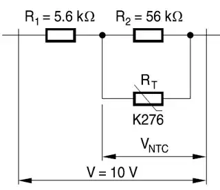
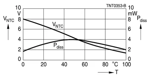
The curve is virtually straight from 0°C to 60°C, which is sufficient for many applications.
In this answer I show how in some cases you can get an almost perfect (15 ppm) linear curve over a limited domain with just a series resistor.
edit
If you don't have the money for a resistor you'll either have to use the Steinhart-Hart equation Nick and Vicatcu refer to, or use a lookup table and interpolation. Both have the disadvantage that they need more memory: Steinhart-Hart contains a logarithm, for which you'll need a floating-point library (I assume your microcontroller doesn't have a floating-point ALU). The lookup table needs some memory as well, and may not give you a better precision than the linearized function if you have to interpolate that.
abdullah kahraman
- 5,930
- 7
- 59
- 104
stevenvh
- 145,145
- 21
- 455
- 667
-
-
And please edit your post for accuracy: the relationship does *not* become a simple linear equation. The relationship *approximates* a linear equation over a particular range of temperatures. – Jason S Jun 18 '11 at 16:17
-
4Jason: can you elaborate? Why not linearize in digital circuits? – Stephen Collings Jul 16 '12 at 13:44
-
App note says that this configuration will suffer from sensitivity a little. – abdullah kahraman Oct 06 '12 at 08:50
-
@abdullah - Yes, due to the parallel resistor. But if you have 10 V available like the graph shows you have nearly 5 V difference over a 60 °C range, that's 83 mV / °C. Even at 5 V you'll have 41 mV / °C. A 10-bit ADC with a 4 V reference has a 4 mV / LSB resolution, so that's a 0.1 °C resolution even without a difference amplifier or InAmp. I don't think the reduced sensitivity is a real problem. – stevenvh Oct 06 '12 at 09:06
-
@stevenvh Yeah, it's great that you mentioned that. That is a big relief for me. – abdullah kahraman Oct 06 '12 at 09:42
-
-
2@abdullah - I meant that ironically :-). But apparently more users seem to prefer the more complex situation, which I don't mind, but then the only reason I can think of to dismiss the more simple solution is that the resistor would too expensive. :-) – stevenvh Oct 06 '12 at 09:54
-
1I have the same NTC with OP. I've managed to get a 0.1 °C resolution for my Ni-MH battery charger's temperature sensor, with a simple equation. Accuracy is not that great, but eh who needs it. `Temp in °C = 83-(x*106/1024)`. Dividing by 1024 is easy :). [Here](http://fooplot.com/plot/o565swbsqg) is the graph. And I only used a 8k2 resistor in series.. – abdullah kahraman Oct 06 '12 at 21:58
4
An NTC has a non-linear response to temperature.
You can work out the resistance of a thermistor by measuring the voltage across it in a potential divider circuit. Then, you can get a resistance \$R\$ from this using Ohm's law.
For example, say you have a 5V supply use a 1k resistor in series with the NTC and if you measure 0.5V, just divide 1k by 0.5V and get 10k ohms as the resistance.
You also need, \$T_0\$ and \$R_o\$, a 'fixed' temperature in kelvins and at that temperature, its resistance. It's usually given at room temperature.
Then, given these details, put it into this equation to get T, the temperature.
\$T=\dfrac{1}{\dfrac{1}{T_o} + (\dfrac{1}{B} * \ln\dfrac{R}{R_o}) }\$
abdullah kahraman
- 5,930
- 7
- 59
- 104
Thomas O
- 31,546
- 57
- 182
- 320
3
There are a number of ways (both in terms of analog circuits and in terms of software computation) to use thermistors to measure temperature.
The short answer, is roughly as follows:
- Use the thermistor and a reference resistor to make a voltage divider.
- Take the middle of the voltage divider and feed it into an analog-to-digital converter.
- Measure the ADC voltage in software.
- Using your knowledge of the reference resistance, and the thermistor's R vs. T curve, convert from ADC counts to temperature.
There are a number of subtleties here, so for further reading you may want to check out this article of mine on thermistor signal conditioning -- hope this helps!
Jason S
- 13,950
- 3
- 41
- 68