2

I'm using a simple DC motor and the wheels from a small toy car to build a basic ping pong ball launcher.

I've got one of the wheels rotating clockwise, mounted directly on the motor's spindle, and the other wheel is free running (with 40mm distance between the two outer rims). So it does sort of launch the ball, but because one wheel is not connected to the motor it has a real large side spin.

How would I connect the second wheel to the same motor so that it spins in the opposite direction?

JK01
  • 121
  • 1
  • 1
  • 3
  • 1
    I'd think that you're going to want *some* spin on the ball when it's launched, otherwise it will drift all over. – Nick T Jan 06 '11 at 15:36
  • @Nick T - with a *ping pong ball* it's probably going to drift all over no matter what =P – JustJeff Jan 16 '11 at 22:59

4 Answers4

6

You can connect the two with gears, or, since the ping pong balls are light weight, just find a pair of wheels with a diameter about 40mm greater than your current wheels and let the friction play the role of gear teeth. Four wheels would reduce the load your bearings need to apply to keep the shafts aligned; just put the small wheels in the middle.

Diagram

Alternatively, you could just forgo the second axle altogether, and spin the ball against a static plate. It would have a lot of spin when launched, but that might be useful, especially if you can get backspin on it so it curves upwards in flight.

Kevin Vermeer
  • 19,989
  • 8
  • 57
  • 102
  • How does larger wheels help? More time in contact with the ball? I'm trying to visualize 4 wheels but I'm not sure what you mean, how would they be configured? – JK01 Jan 07 '11 at 04:00
  • No, the 40mm number was so that your ball would fit between the wheels. The 4 wheel system would use two axles, and each would be configured big wheel-small wheel-big wheel. If this was an electronics question, you'd get a beautiful schematic or PCB that would look great, but it's not, so prepare to be subjected to an MS Paint mechanical diagram. Sorry for that. – Kevin Vermeer Jan 07 '11 at 19:39
  • A variation on this would be to do away with the wider-diameter pieces, and spring-load the undriven wheel against the one with the motor, so that the undriven wheel spins up by contact, but when a ball enters the gap, it can 'swing out of the way' a little bit. The energy for the kick from the undriven wheel comes from its inertia, so you'd probably want to weight it a little. – JustJeff Jan 16 '11 at 22:58
4

Another (easier) option than gears is a figure-eight belt.

Basically, it's the same as a normal belt, but the belt crosses between the pulleys.

z

It also works with v-groove belts, and round belts, assuming they slide over themselves easily.

Connor Wolf
  • 31,938
  • 6
  • 77
  • 137
  • @JK01 provided that the motion of one belt over the other doesn't involve contact. If it does, they will wear, and you will get particulates in the mechanism. But for your application the particulates bit probably doesn't matter. – Dave Jan 07 '11 at 05:08
  • i agree with the figure 8 pulley-belt thing. –  Jan 17 '11 at 01:53
  • With a flat-belt, the system is surprisingly low-wear, with belts often failing from age before mechanical wear. With other belt types, it varies, depending on the belt tension, sheave spacing, and bely shape and material. In all cases, however, the rubbing force is fairly low, so the wear is pretty minor. – Connor Wolf Jan 17 '11 at 10:05
0

You also could use a second motor, if you have the room on your project,

jsolarski
  • 2,510
  • 2
  • 16
  • 19
0

Sorry I don't have a way to illustrate this, but here goes ..

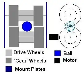
Assume your two ball-launching wheels are in a horizontal plane. Now imagine that the DC motor is under one of the wheels, with its shaft also horizontal, but in line with the two ball-launching wheels' centers, so if you put a small wheel on the motor's shaft, it will be upright. If this small wheel contacts one of the ball-launcher wheels, it will drive it, sort of like a bevel gear. From here, you should be able to see that if you put two such drive wheels on the motor shaft, such that each contacts one of the ball-launching wheels, just either side of the gap between the launch wheels, then the launch wheels will turn in opposite directions, i.e., in the gap, the rims of the launch wheels will go in the same direction, thereby projecting the ball out of the gap.

Well, ok, here's some questionable ascii art. You are looking at the business end of the machine, the ball comes at you from where the '*' is. The launcher wheels are seen horizontal, rim-on, on top, and the drive wheels are also seen rim-first, but are vertical and below.

=====|===== * =====|=====
        -|-----|--[motor]

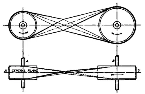
Note that if you do it this way, you can vary the relative speeds of the launch wheels by varying the contact points with the drive wheels. If one drive wheel is 10cm from the axis of its launch wheel, and the other drive wheel is only 9cm from the other launch wheel axis, the ball will get some side-spin.

JustJeff
  • 19,163
  • 3
  • 48
  • 75