10

The circuit below is an oscillator. When I simulate it with ltspice, it does indeed generate a waveform (although it doesn't seem to be a very pure sine wave).

What I fail to understand is why it oscillates.

All the basic literature I have read so far on oscillators (Colpitts, Clapp, Hartley, etc ...) seem to indicate that oscillator circuits need to have both capacitors and inductors in the "tank" part of the circuit.

Also, if you look at the theory, it seems like you need to have both caps and coils to make a tank that has a proper resonant frequency (the 1/Sqrt[LC] formula), but this circuit's "tank" is only made from resistors and capacitors.

When I compute impedances for the tank of that circuit using H-topology formulas, it seem to be tuned to look like one big capacitor (except of course for the short to ground in the middle of it),

If anyone could explain why this circuit oscillates, and how, I would really appreciate it (both intuitive/practical and theoretical explanations are very welcome).

schematic

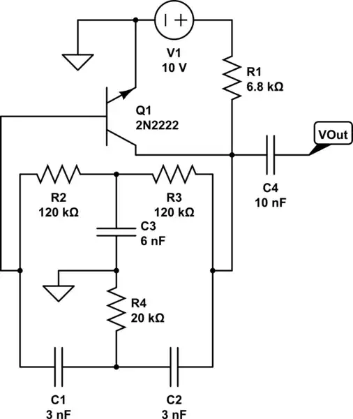
simulate this circuit – Schematic created using CircuitLab

blondiepassesby
  • 757
  • 7
  • 18

1 Answers1

14

It's a phase shift oscillator.

Normally, feedback from the collector to the base acts "negatively" and this is quite important for some amplifiers. This is because the collector signal is the inverse of the base signal (also known as 180º out of phase). Anything fed back does so without causing oscillations. This type of feedback is also used in op-amps for controlling gain.

On the circuit in the question there are a bunch of components that take the collector signal and phase shift it enough so that at a particular frequency, it appears in phase with the base signal and reinforces it. This makes it oscillate.

On a more technical level, the feedback formed around R2, R3, R4, C1, C2 and C3 act as a "mild" notch filter. It should be said that the intent of a "good" notch filter is to totally remove one frequency (such as 50Hz or 60Hz when mains AC is a problem). The frequency which is notched out will be phase shifted by 180º and if it isn't totally notched-out (as in a good notch filter) what remains will feed back and reinforce the original base signal causing it to oscillate.

It doesn't matter that the signal might be attenuated by 20dB, there will still be enough signal left to be amplified and generate a sinewave.

Gustavo Litovsky
  • 7,619
  • 3
  • 25
  • 44
Andy aka
  • 434,556
  • 28
  • 351
  • 777
  • In fact, the 20dB attenuation at the fo (oscillation frequency) is a desired feature in order not to overload too much the positive feedback. In any kind of feedback oscillator, the positive feedback must be carefully controlled: too much of it and the main active device will saturate, too little and the circuit will not oscillate at all (due to losses in the loop). – jose.angel.jimenez Oct 24 '13 at 09:49
  • @jose.angel.jimenez Very true but lack of proper amplitude control is something that makes this circuit unreliable as a pure sinewave oscillator. – Andy aka Oct 24 '13 at 09:55
  • 3
    Useful search term for this topology : "twin T" filter or oscillator. It can be made (in a feedback loop) into a _very_ good notch filter or selective bandpass filter, as well as some very good oscillators (with suitable level control) –  Oct 24 '13 at 10:29
  • 2
    @BrianDrummond : Thank you for this, very useful, led me to [Twin T oscillator](http://en.wikipedia.org/wiki/Twin-T_oscillator) and [Zobel Networks](http://en.wikipedia.org/wiki/Zobel_network) which explain a lot about the circuit above. – blondiepassesby Oct 24 '13 at 12:34
  • +1 Very good answer. Very accessible to those not familiar with the concept – Gustavo Litovsky Oct 25 '13 at 01:04
  • Yes, but you still have not answered how this oscillation circuit can function w/o any coils. I, too, was taught--in my broadcast engineering classes--many years ago, that "tank circuits" and oscillator circuits required inductance and capacitance. –  Jun 02 '14 at 19:41
  • DrTCH: That is not true! You need a frequency-selective circuit that allowes a loop gain of unity for one single frequency. Thats all (oscillation condition). And this can be accomplished with RC or RLC filters. – LvW Jun 02 '14 at 20:14
  • If you want understand why this circuit (and others) oscillate, you must search the conditions of stability ... AC analysis can help you, but also why it start (transient analysis). –  Jun 20 '21 at 18:28
  • It is a Double-T oscillator ... in theory ... R4=60k = 120 kOhm / 2. as the capacity is double when alone. But you may vary ... –  Jun 20 '21 at 18:37