At the moment, I use 0.1% resistors to get accurate voltage measurement through a voltage divider. However, the cost is high, so I was thinking of using 0.5% or 1% resistors and calibrating out the error in software by using a precision voltage reference during production. Has anyone done this successfully? What pitfalls might I encounter?
Asked
Active
Viewed 2,444 times
9
-
What kind of production tools do you have access to? Can you get/build anything like a bed-of-nails programmer/tester? – Kevin Vermeer Jan 05 '11 at 21:36
-
@reemrevnivek - Not currently. My PCB manufacturer E-tests each board, but it's not guaranteed that the soldering will work. – Thomas O Jan 05 '11 at 22:21
-
40 years ago on through-hole boards, this was fairly common where I worked (industrial electronics). The resistor to be selected would be on turret terminals so it could easily be added later. On an SMT board, it is hard to imagine that it would be cost effective. – Mattman944 Apr 08 '20 at 12:11
4 Answers
6
So you've got:
          R_x         R_fixed
Vcc -----^v^v^----+----^v^v^------- Gnd
                  |
                  |
                  +--- V_sensed --- ADC input
Rx is some unknown resistance (probably a sensor of some kind). And you're using R_fixed at 0.1% right now in order to effectively calculate R_x, but you want to use a cheaper fixed resistor with a lower tolerance of perhaps 1%. In doing so you want to perform some kind of calibration during production to correct for the increased error, is that right?
The way you end up doing this is putting an byte in EEPROM (or some other non-volatile memory) that acts as an "offset" in your calculation, and it's a perfectly viable thing to do. The thing is it's going to cost you some time during production to do the calibration activity. In order to do the calibration, you'll need one of those 0.1% resistors (call it R_cal) of nominally comparable value to your 1% resistor to substitute into the circuit for R_x. Measuring V_sensed, you can infer more precisely the value of R_fixed (i.e. to something like 0.2%).
If R_cal and R_fixed are nominally the same value, you would expect V_sensed to be equal to Vcc / 2. You would store the measured deviation from Vcc / 2 as a calibration offset byte, and always add it to V_sensed as perceived by your ADC.
The pitfall, as I see it, is that there is a bunch of work involved in doing the measurement and subsequently in storing the value. Another thing to consider as a pitfall is that temperature can play a role in causing a resistance to deviate from it's nominal value, so you'll want a reasonably well temperature controlled calibration environment. Finally don't forget to use calibrated measurement equipment, as that's another potential source of additive error. One last pitfall I can think of is that the calibration byte should be stored in units of the lsb of your ADC (so if you have a 12-bit ADC, units of calibration offset byte should be "Vcc/2^12 Volts").
Edit
If you are using two fixed resistors to divide a large voltage down to a lower scale as follows:
        R1_fixed       R2_fixed
V_in -----^v^v^----+----^v^v^------- Gnd
                   |
                   |
                   +--- V_sensed --- ADC input
Re-edited Section
So now you want to use a precision voltage reference (call it V_cal) to stimulate V_in during a calibration step in production. What you've got there is in theory:
V_sensed = V_predicted = V_cal * R2_fixed / (R1_fixed + R2_fixed) = V_cal * slope_fixed
But what you've got in reality is:
V_sensed = V_measured = V_cal * R2_actual / (R1_actual + R2_actual) = V_cal * slope_actual
In effect you have a different transfer function slope in reality than what you would predict from the resistor values. The deviation from the predicted divider transfer function will be linear with respect to the input voltage, and you can safely assume that 0V in will give you 0V out, so making one precision voltage reference measurement should give you enough information to characterize this linear scale factor. Namely:
V_measured / V_predicted = slope_fixed / slope_actual
slope_actual = slope_fixed * V_measured / V_predicted
And you would use slope_actual as your calibrated value to determine the voltage in as a function of the voltage measured.
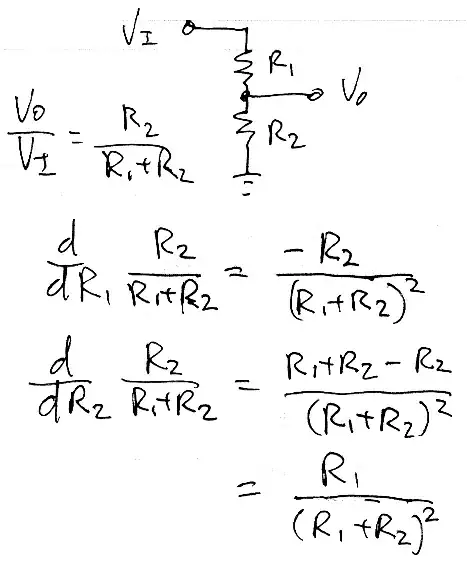
below courtesy of @markrages
To get the actual slope sensitivity to resistor values requires partial differentiation:
-
I want to use 1% for both divider resistors. I am using a voltage divider to read up to 40V signals. Does what you say still apply? And I will be looking around for a precision voltage reference, although ±0.05% is probably okay, and you can get DIP ICs which do that. – Thomas O Jan 05 '11 at 20:40
-
@Thomas OK, I misunderstood your question... you are using a voltage divider to step down a large voltage, not to measure an unknown resistance... I will change my answer accordingly. – vicatcu Jan 05 '11 at 20:47
-
I'm not so sure the error won't be linear, ignoring for now resistor heating. It should be a fixed linear factor for each divider (there are four on the board), as the divider is just dividing by a fixed amount. With zero volts in, zero volts should be measured by the ADC, plus the offset error, which might cause it to read one count, so I don't really need to worry about the offset... Unless I'm missing something? – Thomas O Jan 05 '11 at 22:24
-
sorry, nonlinear was probably the wrong term in retrospect. What you'll effectively get from calibration is a scale factor, right? The deviation from predicted is going to be linear with respect to the input voltage. So given some "predicted V based on the measurement" the actual V is going to have to be multiplied by some factor. What *would* be non-linear is the error in assuming it was an offset voltage. – vicatcu Jan 06 '11 at 13:26
5
By me, it will be difficult, however not impossible.
- Usually 0.1% rated resistors have lower TC = temperature coefficients, are more immune to humidity, soldering (thermal shock), have lower drift with time, ... than 1% rated resistors. So, many sources of resistance change should be considered.
- At 40V level selfheating effect may be meaningfull, therefore resistors with proper power rating should be used.
- there are good quality 1% resistors, having TC <20ppm/deg, and similar TC from resistor to resistor (+- 10ppm difference) but this is true for the same type, nominal value and power resistors. Proper use of this type resistors in voltage divider will cancel influence of average TC. Only difference in TC will have influence on output voltage. So it is possible to get precision dividers, using resistors of the same value.
- Resistors of different nomial values may have more different TC . And selfheating will have different influence - more power dissipated on higher resistance resistor will heat it more ,and change resistance.
Conclusion: If You are using many resistors in production (long series of the same board / divider) and cost of resistors is meaningfull, You can consider replacement. Otherwise most probably it is not worth of efforts.
czgut
- 101
- 1
- 3
4
You can calibrate out:
- Manufacturing tolerance [2] [3], (+/- 1*%) = can be calibrated
- Solder heat [2] [3], resistance change due to soldering (+/- 0.2* to 1%) = can be calibrated
But do not forget about all the other tolerances:
- TCR [2][3], temperature coefficient resistance (+/- 50 to 100* ppm/C)
- VCR [2], voltage coefficient resistance (+/- 25* ppm/V)
- Environmental factors, resistance change during lifetime (<=+/- 3%* at 155 C, 225 000 h) [2] [3] [4]
* Note that all values can differ between resistor brands and products.
[1] https://www.vishay.com/docs/28809/driftcalculation.pdf
[3] https://industrial.panasonic.com/cdbs/www-data/pdf/RDA0000/AOA0000C304.pdf
[4] MIL-STD R-10509
warpi
- 61
- 5
4
That approach works well going from 5% to 1%. Going from 1% to 0.1%, I suspect that you will start to have your accuracy ruined by temperature fluctuations changing the resistance and thus the voltage.
If, for some unknown reason, you're operating in an isothermal environment and your resistors are all constant current, so self-heating is predictable, it's still viable.
pingswept
- 12,581
- 4
- 46
- 64
-
I figure temperature might influence a typical ±100ppm/°C resistor by -0.4% to +0.7% (or the reverse) over the -40°C to +70°C operating range of my device. If necessary, I could calibrate that too. It's more likely it will be exposed to high temperatures, and I can heat the board up to test this. – Thomas O Jan 05 '11 at 20:47
-
3Sometimes with clever design you can get the resistor tempco's to cancel out. If you identify such resistor pairs in your design, put them next to each other in the layout to maximize thermal coupling. Or even use resistor arrays. – markrages Jan 05 '11 at 21:17
-
@markrages, If both resistors are +100ppm/°C, will that minimise error, since both will be out by the same fraction? In theory, assuming both resistors drift by equal amounts, the output shouldn't change. In practice it probably would, especially since the voltage reference (LM4040) itself may drift. – Thomas O Jan 05 '11 at 22:26
-
@Thomas. Yes, that's the idea. Let's see, the LM4040 claims 100ppm/C worst-case, 15ppm typical at 1mA or less. The typical temperature response is plotted in the datasheet and doesn't look like something that could be easily canceled out. I guess you could glue an NTC thermistor to it and "ovenize" it to keep it at a constant (elevated) temperature, but not if you're on a power budget. – markrages Jan 06 '11 at 04:08