13

schematic

simulate this circuit – Schematic created using CircuitLab

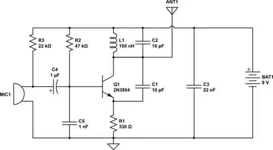
This is a minimalist FM transmitter I've found from http://www.talkingelectronics.com/projects/Spy%20Circuits/SpyCircuits-1.html

I'm a bit confuse about three things

1)How does this modulates the base input signal to frequency modulation ? Because I don't see any change happening neither in Inductance nor in Capacitance of that LC tank oscillator. Is that because of C1 somehow ?

2) For what purpose capacitor C5 is used ?

Parth Parikh
  • 419
  • 4
  • 14
  • 3
    The most minimalist FM modulator I've seen uses a microphone like a variable capacitor - the microphone directly changes capacitance with sound levels and of course modulates the carrier frequency. – Andy aka Oct 21 '13 at 19:40

1 Answers1

9

The frequency of this generator is determined by \$C_2||C_{bc}\$ of the transistor. \$C_5\$ connects the \$C_{bc}\$ in parallel with L and C2.

As long as the junction capacitance is voltage dependent, changing the base voltage changes \$C_{bc}\$ and thus the resonance frequency of the oscillator.

Of course, the quality of this modulation is not very high, but for such simple device it is acceptable.

johnfound
  • 5,307
  • 1
  • 16
  • 31
  • 1
    C1 provides positive feedback to sustain the oscillation and R1 gives negative feedback am right @johnfound – yogece Oct 21 '13 at 19:18
  • If I add a resistor instead of C5 then will it be OK or this won't work ? – Parth Parikh Oct 21 '13 at 19:20
  • @ParthParikh that would be okay i think.let us wait for other answers – yogece Oct 21 '13 at 19:22
  • 1
    @yogece - the transistor in this oscillator works in common base, so the emitter is an input for the positive feedback. Also, the resistor sets the DC working point. – johnfound Oct 21 '13 at 19:23
  • @ParthParikh - With a resistor, the positive feedback will not work properly. The capacitor provides phase rotation besides the simple AC coupling. – johnfound Oct 21 '13 at 19:25
  • @johnfound are you sure this is a Common Base ? it looks like Common Emitter to me because input coming from mic is likely to be given to the base through that small filtering capacitor resistor pair. – Parth Parikh Oct 21 '13 at 19:30
  • 4
    @ParthParikh - it depends. For the low frequency signal it is emitter follower (common collector) and for the high frequency signals it is common base. There is no common emitter though. – johnfound Oct 21 '13 at 19:33
  • 2
    @ParthParikh You can add a resistor as well as keeping C5 but C5 is needed because it is a common base amplifier that produces oscillation and C5 must decouple the RF signal from the base for it to work. C5 isn't so big as to destroy microphone signals but these are nowhere near the same frequency as the oscillator (typically). – Andy aka Oct 21 '13 at 19:38
  • how is C2 in parallel with Cbc ? – emperor_penguin Mar 28 '14 at 19:28
  • 3
    @emperor_penguin For high frequencies all big capacitors (c3 and c5) are short circuit actually. Replace them with wires and see what happens with the circuit. – johnfound Mar 30 '14 at 08:50