17

Are there any disadvantages in using the following method to accomplish a perpendicular board-to-board connection?

(i.e., any disadvantages in terms of

  • board manufacturing capability/cost
  • assembly convenience
  • mechanical stability
  • contact reliability
  • and any other potential issues in long-term use of the boards that I am not seeing)

enter image description here

DETAILS:

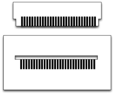
Since there are only a few contacts needed and within a limited space, I am trying to do this:

  • Design 1st board with a "pseudo-connector" by shaping copper-pad protrusions directly within the board's dimension
  • Then make complementary-sized vias on the 2nd board
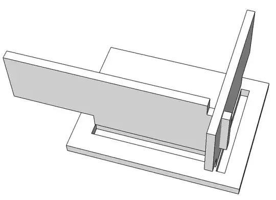
  • Finally, insert the conductive protrusions of the 1st board into the 2nd board, and solder

NOTE 1: Each of the two boards will be mechanically bound using screws to the enclosure's top and side walls, respectively.

NOTE 2: Another related solution for the board-to-board connection might be to have castellated vias at the edges of baords, which can be soldered with the boards at right angles, although this approach might make alignment less convenient during assembly. Perhaps this method has some advantages though?

NOTE 3: I didn't wish to use headers/receptacles/plastic-connectors, because they would bring up additional part costs and assembly steps.

redwo
  • 171
  • 1
  • 4
  • I saw that in a DualShock controller once. Except they used the entire board, with contacts spaced along it on both sides. But it was just for a crystal. – Ignacio Vazquez-Abrams Oct 19 '13 at 19:59
  • Is this what they did: They made one continuous rectangular cutout in the horizontal board (with several pads placed along the length of the cutout), and then inserted the vertical board's conductive protrusions like above, except all into the one cutout? – redwo Oct 19 '13 at 20:03
  • That's exactly what they did. – Ignacio Vazquez-Abrams Oct 19 '13 at 20:04
  • I like the elegance of that approach. The one benefit I see to mine is that drills/vias are usually free among most board manufacturers. A rectangular island cutout may not be; I've to investigate this. – redwo Oct 19 '13 at 20:06
  • Hmm, alternatively, I could do the horizontal board with edge castellations [like in this image](http://i.stack.imgur.com/YZKA3.jpg), and continue with the rest as above. – redwo Oct 19 '13 at 20:08
  • [Here.](http://www.xmods.co.za/1181-1562-thickbox/refurbished-ps3-dualshock-3-controller-board-msu-vx4.jpg) It's down at the bottom, between the analogs. – Ignacio Vazquez-Abrams Oct 19 '13 at 20:10
  • [And the back side.](http://www.xmods.co.za/1181-1561-thickbox/refurbished-ps3-dualshock-3-controller-board-msu-vx4.jpg) – Ignacio Vazquez-Abrams Oct 19 '13 at 20:11
  • @IgnacioVazquez-Abrams: Thanks! Time to ebay one of these controllers and open it to see the finer details up close. But it's a good sign if Sony did a similar method. (Although they also seem to have a [board variant](http://i217.photobucket.com/albums/cc308/rebuser/myds36axisfront.jpg) with the crystal on the main board itself.) – redwo Oct 19 '13 at 20:17
  • 3
    @IgnacioVazquez-Abrams: Also, kudos on having the attention to detail to notice/remember something so minor on a gaming board! – redwo Oct 19 '13 at 20:19
  • 2
    The only thing I'd be worried about is that after soldering and then bolting to the case, you're going to have tension on the joint (the angle between the boards is unlikely to precisely match the angle of the case). That means that the solder joints may crack over time. Probably not a big deal, but worth a thought or two. If you can, I'd mate the boards, attach to the case, then solder. Probably not possible, but it eliminates the problem if you can. – Michael Kohne Oct 19 '13 at 20:43
  • How are you making those board edge male pins? They will be BLOODY expensive to make. – yhyrcanus Oct 19 '13 at 21:56
  • 3
    Those edge pins are just edge routing. You would only have copper on the top and bottom... not on the sides I believe. – Spoon Oct 19 '13 at 23:20
  • I suspect that just doing copper fingers on the "male" edge and using an edgecard socket on the other board would be cheaper and more robust than your proposal. But I can't prove it. – The Photon Oct 20 '13 at 02:28
  • 1
    How will you design your "male" board to get solder to wet over the cut edge like is shown in your picture? – The Photon Oct 20 '13 at 02:29
  • @ThePhoton: The solder indeed won't wet over those two faces of each protrusion. That is an issue -- but I'm guessing it won't be a significant one, since the two faces that *do* have copper on them will probably be sufficient for the electrical contact, and for somewhat of a mechanical bond. – redwo Oct 20 '13 at 07:25
  • This is a MUCH BIGGER assembly step than connection at a header, and takes a much more skilled worker to do. It will also take too much time to do. You'll get all sorts of angles that are well off 90 degrees, with no good way to fix them. Stresses may peel the copper right off your boards. If you do this, test it to death before assuming it will work. – Scott Seidman Oct 20 '13 at 11:54
  • Would you buy a table or a chair whose legs are just connected like that without any other supporting parts? – hkBattousai Oct 24 '13 at 19:47

4 Answers4

17

You don't mention board type etc. here is some feedback:

You have to be aware of the shear stresses which can cause de-lamination of the copper traces from the board underneath. You do have a huge lever arm to develop high forces. This could be reinforced with vias in those fingers, if you have vias available that is ....

However, this sort of approach is best done in a pierce and blank assembly line (probably with single sided copper) and phenolic boards. The reason for that is that it is possible to have the stamping operation get you nicely square corners on the cutting die.

In a past project, this is what we did. Do keep in mind that cost was critical, we were counting 1/10th of a cent for resistors as being too much whereas labor cost was not an issue. The device itself was potted for protection/longevity and safety.

enter image description here

Rather than have individual "pins" as you drew we had slots. We used the precision of the stamping tool along with a precise jig for soldering (by hand).

Also, there were three boards that interlocked and self supported. So that once assembled (without solder ) they were very robust. It took some work to get right, but putting a connector in there was a non-starter because of the extreme cost pressures.

here is a quick sketch of 3 intersecting boards and slots.

enter image description here

Here is a picture from a development board that I still had kicking around. These boards where done in FR-4 to allow us to study thermal and mechanical effects before moving to the expensive pierce and blank dies and phenolic boards (I didn't keep any of those unfortunately), other wise you'd see square corners and tighter tolerances. This was also used to study solder wetting and the assembly process tolerances and ease of manufacturing.

enter image description here

This board is quite beat-up from being at the bottom of a drawer for many years.

So yes it is doable, to the tune of 100Kunits per month.

placeholder
  • 29,982
  • 10
  • 63
  • 110
10

I have seen boards connected at edges with pads and a lot of solder, but this is a last resort and not a good idea in most cases.

First, it is difficult to ensure all the solder joints are good. These joints will need to be done by hand, which means human error and inconsistancy of workmanship will be issues. A bad solder joint can make a connection some of the time, so passing a simple functional test in production doesn't mean much.

Second, this kind of structure will be exceptionally vulnerable to mechanical stress. Solder joints crack easily with just a little stress. You would have to externally hold the boards rigidly while they are being soldered and then forever afterwards. One slipup, and you can't count on them anymore. Even then, thermal cycling and vibrations of normal use could cause trouble.

Third, getting the board made with the fingers may not be so cheap. Each finger adds 4 route points, which the board house will likely charge for when there are large numbers of them. Since the fingers will be routed, the inside corners will be rounded. This means the fingers have to be longer so that there is enough straight part past the rounded corners. I would also worry about possibly cracking the board itself due to stress when the two boards aren't held perfectly at right angles.

There are right angle header connectors available for just such purposes. These are basically stiff header pins bent at a right angle and held together with plastic. They are soldered into holes in each board. When the resulting joint is flexed a bit, the stress is mostly taken by the bending of the header pins.

Olin Lathrop
  • 310,974
  • 36
  • 428
  • 915
4

You should add in a right angle header that is soldered to holes in both of the boards. This will result in a much better, stronger, and flexible connection.

Take a look at header prices at on-line sites and you can see that they can be really low cost if acquired from the correct places.

If you try to create the fingers via edge routing there will be a radiused inside corner in each finger. Common edge routing bits are 50 or 100 mils so this puts a 25 or 50 mil radius in each finger corner. This will prevent the boards from mating edge to edge like you show in your pictures.

Michael Karas
  • 56,889
  • 3
  • 70
  • 138
-1

Short Answer will be YES.

You can connect a peripheral board like this but be sure that you don't need to unplug and plug it quite often.

dmSherazi
  • 303
  • 4
  • 17