17

I'm working on a development board, and need to let users set some configurations.

It will be used by students and engineers who are trying to build circuits on a breadboard; I'm not dealing with consumers. Usually, the settings will stay the same, but it's possible that every new project could use a different configuration.

I will be dedicating some pins to interfaces like USB and Ethernet, but I'd like to give users the option of using those pins for a different purpose. Some kind of configuration will be required. The options I've considered so far are:

Solder bridges:

0-ohm resistor
Either 0603 resistor packages to allow 0-ohm resistors to be used, or nearby pads for a solder blob.
Pros:

  • Cheapest option possible
  • Smallest PCB area required
  • No accidental changes
  • Customizable by soldering directly to pad

Cons:

  • Requires soldering iron to make changes
  • Possible to damage board with repeated soldering/desoldering
  • 0-ohm resistors require having those parts on hand.

DIP switches:

alt text
Tiny mechanical switches in an IC package.

Pros:

  • Easiest to change
  • Fairly durable

Cons:

  • Most expensive option by far
  • Might be changed by accident
  • Large area on PCB
  • Lowest current of the options
  • Hard to make changes to PCB

Pin Jumpers

pin jumper for IDE hard drive
Removable Jumpers for .1" headers like those found on PC motherboards and drives.

Pros:

  • Less expensive than DIP switches
  • Easy to make changes to PCB
  • Good balance between easy-to-change and semi-permanent
  • Easy to see configuration

Cons:

  • Large PCB area required
  • Tallest profile; usually .5" or so required vertically
  • Jumpers might be lost

Electronic Bus Switching
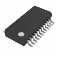
TI SN74CBT3384ADBQR
Use FETs or a bus switching IC like the TI 74CBT series, and control with an EEPROM/microcontroller. Suggested by Brian Carlton.

Pros:

  • Small PCB area
  • Configurable in software
  • Can put both to High-Z or connected

Cons:

  • Requires another couple ICs; medium cost.
  • Less current than other options
  • Has real resistance
  • Can now confuse hardware bugs with software bugs and vice versa

The solder bridge option makes me worry about weakening the pad with repeated resoldering and delaminating it from the PCB. How many times can a good soldering tech change a part on 1-ounce copper with an ENIG finish? Would covering the edges of the pad with soldermask and adding thermal reliefs (for adhesion, not heatsinking) on several sides of the pad increase the durability?

Am I missing anything? What configuration methods do you like to use on a dev board?

Kevin Vermeer
  • 19,989
  • 8
  • 57
  • 102
  • Aren't jumpers 0.1" by 0.2", and DIP switches 0.1" by 0.4"? The one advantage that DIP switches might have is that it's probably more convenient to use SMT versus TH. – Nick T Jan 04 '11 at 19:16
  • 1
    With proper technique, you can change a part on a circuit board unlimited times. With poor technique (iron too cold) you can't change it once without damage. – markrages Jan 04 '11 at 19:24
  • Unlimited times? Hmm, maybe I have to turn my iron up. Is 375C adequate for most jobs? – Kevin Vermeer Jan 04 '11 at 19:28
  • I usually use ~350C with 63/37 solder (80W iron) and think it is a little hot. Not exactly sure what the right temp is! – tyblu Jan 04 '11 at 19:33
  • Eventually the solder will dissolve the copper on the board, so while not "unlimited", dozens of times is still doable (unless you have 0.25 oz. copper or something crazy) – Nick T Jan 04 '11 at 19:36
  • What works for me is a hot iron, and short time. When I have lifted tracks it is because my iron was too cold or my tip was too small, allowing the solder to freeze to the tip a little bit. @Nick T how does solder dissolve copper? – markrages Jan 04 '11 at 20:31
  • 1
    @Mark - The same way water dissolves sugar; it's just slower and only happens at high temperatures. ENIG boards loose their gold coating after as little as 3-4 soldering/braid cycles. – Kevin Vermeer Jan 04 '11 at 20:38
  • 1
    don't forget signal integrity. You mentioned ethernet/USB so some signals may be high speed and the various options will impact the trace's characteristic impedance which may cause problems. – Mark Jan 04 '11 at 23:08
  • Are you going to electrically switch Ethernet/USB lines? I was thinking this was for enable or config pins that weren't going to run at any real frequency. Adding switches or other complexity to high speed lines must be done with care. – Nick T Jan 04 '11 at 23:14
  • @Nick - Yes, I am. It will only be 10Mb Ethernet, and USB 1.1. The processor is running at 72MHz, so there's a good potential for some fast edges. I plan to put some current limiting resistors on all the breadboard I/O to slow the edges down a little. – Kevin Vermeer Jan 04 '11 at 23:30
  • I think you should separate solder-blob jumpers from 0 ohm resistors. While they both do require soldering, 0 ohm resistors can be used in a manufacturing run, while there is no way to pre-set solder blob jumpers short of manual soldering each one. For dev boards you are hand-stuffing, either is fine, but if you make a few of these things, the ability to have them populated by machine could be important. – Connor Wolf Jun 16 '11 at 23:44
  • Why are my numeral zeroes being converted to letter oh? – Connor Wolf Jun 16 '11 at 23:45
  • @Fake Name - Based on the source of your comment, and a comparison of '0 ohm', they're not the letter oh - they're a zero, but a bad one at that. zero-oh: 0o. If you typeset them in LaTeX they'll look beter: \$\mbox{zero-oh: }0o\$ Slashed zeroes across the board would be nice, though. – Kevin Vermeer Jun 16 '11 at 23:52
  • @Kevin Vermeer - Geez, what a horrible font. – Connor Wolf Jun 17 '11 at 05:08
  • @KevinVermeer What do you mean has real resistance for the electronic bus switching? – Dean Nov 24 '11 at 00:28
  • @Dean - The others are mechanical connections. In my example, I was talking about disabling USB or Ethernet interfaces with the jumper. The electronic bus switches (the cheap ones at least) have significant ("real") parasitic effects: You're passing your signal through a transistor. In contrast, a solder jumper has approximately zero effect on the signal. – Kevin Vermeer Nov 24 '11 at 00:33
  • Jumpers become loose. Right now I'm debugging some old boards malfunctioning on the field, all of them were exposed to high temperatures and all jumpers became loose. In new boards we are using high temp. switches now. That may not be a problem for development boards, but jumpers may become loose too if changed frequently. – MV. Aug 15 '17 at 11:29

6 Answers6

14

For straight-up development boards (for your internal use), I go with a solder jumper or put two back-to-back (3 pads) to make an SPDT switch (here's a footprint I use). If it's small enough, it's fast to both close and open with a touch of solder or desolder braid. Using an actual resistor makes it much more difficult to rework with a standard iron.

If this is a product (as in, the Atmel STK500 development board is a product), you should use something like jumpers or DIP switches, because you don't want some dumb user poking around your board with a 1000°F iron. I'd tend towards DIP switches if you have more options or you are going to put it in an enclosure, otherwise jumpers would be cheaper.

The main question should be "is this something that will be changed as part of normal use?" If the answer is yes, requiring a soldering iron and skills is inappropriate. If it's something that an end user might modify 1-5 times (or preferably someone skilled, e.g. a lab tech), a solder jumper might be OK.

Nick T
  • 12,360
  • 2
  • 44
  • 71
  • 1
    This is a development board; it will be used by students and engineers. That doesn't mean that they're all good with a soldering iron, though. How many times can you flip that solder-blob SPDT switch before the pad comes up? – Kevin Vermeer Jan 04 '11 at 19:26
  • 1
    @reem, I think you bring up the main point; if changing this is something that is going to be expected as part of normal use, a solder blob is inappropriate. Updated my answer. – Nick T Jan 04 '11 at 19:38
  • If it's for students purpose, leave it at jumpers. I think you can expect those people are qualified enough to figure out how to place the jumper, where, etc. I think a DIP switch is too fancy/expensive. Soldering is inpractical. If you want to change a setting you 'should' unplug the board and rework it in the solder lab. For me: Solder for one time configuration, jumper settings for adjustment in a particular testcase, DIP switches if it requires some user interfacing. – Hans Jan 04 '11 at 19:51
  • You had the best answer overall, so I gave you the check, but I actually am going to use Brian Carlton's answer for the configuration stuff and 5016 resistor networks for the configuration (since I want a few dozen ohms anyways to slow down the edges and stop ESD events) – Kevin Vermeer Jan 06 '11 at 00:18
6

I've grappled with this question a few times myself. Clearly, there is a time and a place for all of these techniques. That being said, there are no hard and fast rules or conventions I know of that are standardized (or even necessarily broadly agreed upon). My take is:

  • The solder-bridge/0-ohm technique is appropriate for building in an "option" into a board that is "supported" but not the typical use case. This is often called a "population option" so the idea is generally you either add the bridge once or not at all. It's not typically used for settings that change more than a couple times. An example might be an alternative signal routing through an optionally populated transceiver.
  • The jumper/header technique is appropriate for situations where you want to be able to "break-in" to a signal, or for a very few "this-or-that" type settings. Also, think of using this when the setting changes infrequently. Example maybe a current probe break-in point or a "voltage select" setting.
  • The DIP switch technique is appropriate for configuration settings that may change often and require a beefy/permanent user interface. Example maybe "address bits" for an IC.

Again, not an authorative answer, but my opinion / rules of thumb.

vicatcu
  • 22,499
  • 13
  • 79
  • 155
3

Solder pads are out. Just say NO. You absolutely do not want to force anyone to use a soldering iron in order to be able to use your board, EVEN IF they are good with a soldering iron.

The EEPROM/FET idea is also not a good idea, because it is not readily observable. What is the state of that FET? You need a SW suite to find out, and maybe that is not enough: what if something funky happened between what you told SW you wanted and what actually happened at the FET?

So your choices are DIP switches or pins and jumpers. You could also do pins with a wire wrap gun. I would slightly prefer the DIP, but take your pick. Any of these three is miles better than solder/SW.

Vintage
  • 802
  • 4
  • 4
  • 3
    I understand your points, but I think you're ignoring opposite arguments (size and cost). There are always tradeoffs. – Kevin Vermeer Jun 16 '11 at 21:10
3

How often will it be changed? If only very occasionally or even just once then a solder pad is fine. If you expect it to be changed often I would go with the dip Switch. The jumpers are somewhere in between.

Jim C
  • 1,997
  • 12
  • 11
  • 1
    It will be changed about one time for every project or breadboard job (assuming no mistakes are made). New source code has to be written, and new circuits built on the breadboard before you'd want a new design. – Kevin Vermeer Jan 04 '11 at 20:40
3

Don't use DIP switches for something going out of house. Users will change them.

I would put solder holes for jumpers, but only install them on the prototype if you are changing them frequently. But for what you describe (i.e. board variants) I would go with putting the settings in your EEPROM -> can set in software, less area.

Brian Carlton
  • 13,252
  • 5
  • 43
  • 64
  • 1
    Sorry, maybe I wasn't clear enough. It is going to other engineers and developers, so changes are good. – Kevin Vermeer Jan 04 '11 at 22:42
  • I like the EEPROM idea; maybe connect something like [this bus FET](http://focus.ti.com/lit/ds/symlink/sn74cbt3384a.pdf) switch from TI? I've added it to my list, thanks for the idea! – Kevin Vermeer Jan 04 '11 at 22:53
2

For things which only need to be changed "one way" [i.e. changed once but not changed back], I've sometimes seen boards with a physical wire soldered between two points and marked for cutting. That's may only work well for through-hold boards, but with the right placement equipment it might work with reflow. (I've seen through-hole resistors reflowed by using a cutout under the resistor body so the leads would sit flat on the board; if the jumper wire would stay in place during reflow I wouldn't see any reason it couldn't work).

Kevin Vermeer
  • 19,989
  • 8
  • 57
  • 102
supercat
  • 45,939
  • 2
  • 84
  • 143