4

I'm using a non inverting opamp circuit with a LM741 opamp to make an output signal have twice the amplitude as the input signal.

The problem I am having is the output is twice the amplitude upto around 7kHz and after this point it begins to decrease with increasing frequency, anything I can do to stop this happening or a counter measure to fix it?

user27365
  • 113
  • 4
  • 10

1 Answers1

3

Even the 741 shouldn't be this bad but you could be running into slew rate limit problems. Firstly, for small signals, you should be able to get a gain of about 40dB. Here's the open loop gain response: -

enter image description here

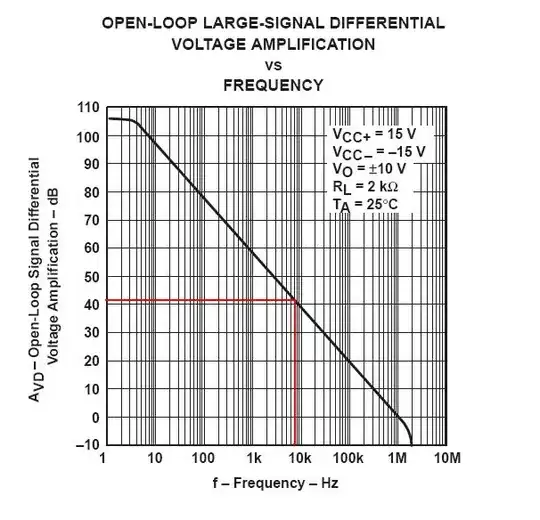
Without any feedback at all, the 741 should still provide amplification of about 40dB at 7kHz. Shown on the graph above are two red lines that correspond to 7kHz and about 40dB. This is the small signal amplification that is possible with the 741. The graph is taken from the uA741 (because I couldn't locate an adequate picture of the LM741 so you need to do a bit of research to verify it is about the same. I believe it will be but please do check.

If you are trying to amplify with a gain of 2 (6dB) I'd expect a flat response up to about 300kHz (3dB point). You can also see this from the above graph by running your eye along from where 6dB is on the vertical scale and seeing where this crosses the thick black line and reading the frequency value on the X axis.

Slew rate limiting - this could be your problem - try reducing the signal amplitude to (say) 1Vp-p - does this improve things? Slew rate limits for the 741 are about 0.5V per microsecond and this means that if you are trying to produce an output that is 10Vp-p, the output rise time will be no faster than 20 microseconds. Correspondingly the fall time will also be 20 microseconds with the resultant approximate maximum frequency of \$\dfrac{1}{40\times 10^6}\$ = 25kHz. Again, this doesn't sound like the problem but please do check.

Finally, parasitic capacitances may be affecting your choice of feedback resistor. If Rf is in the order of 1M ohm and there is 10pF effectively across the 1M, the 3dB point of the op-amp circuit will only be around 15kHz.

In conclusion, I would start to suspect slew rate as your problem and maybe you are using resistors that are too high in value. Other than that you should get a reasonably flat frequency response to over 100kHz for a gain of 2.

Andy aka
  • 434,556
  • 28
  • 351
  • 777
  • Thanks for your reply. I should have noted that the gain is 28.29dB since the original signal is attenuated in another part of the project before it is fed to the amplifying circuit. From your comment I believe that 28.29dB still shouldn't cause problems. I tried reducing the resistors by an order of 1000 which made no difference. The input is also approximately 300mV and this amplifier is to increase it back to the original amplitude(or two times the amplitude if it doesn't cause issues which would be a gain of 35dB) – user27365 Oct 18 '13 at 22:59
  • there ya go... 35dbB gain and you are starting to attenuate at 7KHz a bit. This sounds like the problem. There are far better op amps available. – Andy aka Oct 18 '13 at 23:08
  • Unfortunately this is part of a university project and I can't use another opamp. Is my best option just to use a few non inverting amplifier circuits in series to get to the desired gain? – user27365 Oct 18 '13 at 23:16
  • Two op-amp gain stages in series would work;each with a smaller gain giving you the 35dB you need. – Andy aka Oct 18 '13 at 23:23
  • I'm currently using two non inverting circuits in series with the same amplification. When only the first circuit is connected the output is constant up to the value of 20kHz I need however when I connect the second the output of both combined is half the value it should be, any idea why? – user27365 Oct 21 '13 at 07:29
  • @user27365 Nothing helps more than a circuit diagram! – Andy aka Oct 21 '13 at 07:31
  • [Here is a screenshot](http://gyazo.com/602d058c2959a81ae4782e24d5110345) The very left circuit element is the receiver of an LED signal which has a DC offset hence the two passive low pass filters before the amplifiers. – user27365 Oct 21 '13 at 09:42
  • @user27365 Nothing appears to be wrong with the circuit - maybe it is slew rate limiting in the 2nd stage? I note that the total gain is 21.8dB and you wanted 28.29dB - maybe you have made an error in your resistor calculations? – Andy aka Oct 21 '13 at 10:53
  • Why would it limit the second opamp and not the first though since they both have the same gain? + I get the desired output at low frequencies. – user27365 Oct 21 '13 at 10:55
  • @user27365 slew rate affects higher amplitude signals - the output voltage level can only change so-many volts per microsecond and if the signal is small it never has a problem but on your 2nd stage, the voltage output is intended to be 3.5 times bigger and it can't shift the bigger amplitude - it hits limits - I bet the waveform looks triangular a bit maybe? – Andy aka Oct 21 '13 at 10:58
  • Yes it does look triangular. I'll try amplifying more on the first stage before hitting the slew rate limitation and then do the rest on the second stage – user27365 Oct 22 '13 at 01:57
  • Still not getting the correct output, is there anything else I could do to increase the amplitude for all frequencies with only analogue components? – user27365 Oct 22 '13 at 02:15
  • @user27365. I know I keep harping on about slew rate limits but you've hit the buffers on what a 741 can achieve. Above a certain amplitude and frequency product the signal will not get bigger. Change the op-amp and there's no point arguing if you want it to work. Alternatively, if you are not too bothered by low frequency stuff use a well designed audio transformer to step up the voltage but this canbe tricky with the dinosaur aka 741. – Andy aka Oct 22 '13 at 08:41