My project concerns speed control of a solenoid. In this project, the stroke is 30 mm. I want the plunger to cross 30mm in a few seconds (like 5 seconds).) For this purpose I want to control the current of the solenoid coil with PWM, but it seems that the plunger does not move until the current reaches a certain amount, after which the plunger moves very fast. What is your opinion for low speed solenoid acting? What method should be used? Electrical or mechanical methods?
Asked
Active
Viewed 1.0k times
7
-
2I think you need a proportional valve or servo-actuated valve, solenoids will be designed to work as on/off devices. – John U Oct 17 '13 at 13:50
-
Does the solenoid have any feedback? – Erik Friesen Oct 17 '13 at 14:12
-
If necessary i can use a close-loop, but current driving circuit is open loop – farshid Oct 17 '13 at 14:23
-
You need to attach it to q spring then. – Chris Nov 14 '22 at 16:44
6 Answers
3
I offer this as a proposal of an idea - I haven't had time to try this out so it may or may not work, but hopefully it will spark off a line of thought.
The main problems with solenoids are that they are designed to operate quickly - once sufficient current is applied they snap into action. Their action is not proportional - below a certain current they do nothing. Finally, what they do best is PULL on the plunger.
So here's the idea. Connect two solenoids in opposition to each other in an electrical tug of war.
and this is is my thinking...
With both (equally) powered at the same time (rising edge of pulse) there should be no net movement (because the forces are equal and opposite)
If solenoid B pulse is slighter longer than solenoid A pulse then the plunger should move towards solenoid B. The amount of movement will be small because the time interval is small (Newton's laws). Friction on the plunger will stop motion during the OFF time. Repeating the pulse will keep the plunger moving (in small jumps) in the same direction.
The pulse frequency will determine the jumps per second and the time delay the amount of movement per pulse so together they control the speed of the plunger.
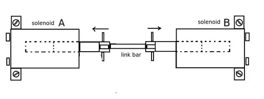

The control circuit (see above) which can be built using a 555 timer and 4071 quad dual input OR gate, is not so much PWM as PLM (pulse length modulation). These pulses would be used to control the solenoid current through MOSFETs (with snubber diodes across the coils). To reverse direction simply switch the pulses over so A is B and B is A. Frequency and CR delay will be down to a bit of experimentation but I'd be thinking in terms of a few 10s of Hertz rather than 100s.
JIm Dearden
- 18,926
- 30
- 40
-
Dear Mr.Jim Dearden Thank you for your creative ideas, i think this proposal is simpler than the PID control – farshid Oct 18 '13 at 08:44
-
2@farshid - but it will not work at all. Sorry. The force of the solenoid (on equal current) depends on the square of the position. This way, is one of the plungers is highly dipped in the solenoid it will pull with higher force. As long as you don't have feedback you simply never know what of the solenoids will out-pull the other. – johnfound Oct 18 '13 at 09:03
2
You need a Linear Servo, e.g. this small one. Solenoids aren't really suitable for gradual movement.
You could, if you wanted a project, build your own linear servo using a motor, worm gear, and linear potentiometer for position sensing.
pjc50
- 46,540
- 4
- 64
- 126
-
Your offer is very useful, but my master forced me to driving solenoid slowly! – farshid Oct 17 '13 at 14:31
-
This is slightly off topic, but would it be possible to use either a linear servo or a solenoid for more than two states? 3 states for example? – Karoh Nov 17 '15 at 22:24
-
@horak, Answering my own question here but I might be better off with a servo! – Karoh Nov 18 '15 at 04:10
2
This is pretty hard project you started. Solenoids are highly hard to be controlled, other than ON/OFF type.
You will need some sensor that to measure where is the anchor of the solenoid in every moment and then some regulator that to control the current of the solenoid in order to reach the needed position.
As long as the force/position of the solenoid is not constant and even not linear, such regulators have tendency to work not very stable.
The regulator itself can be implemented as analog, digital or software device.
The sensor in the feedback loop can be either position sensor, speed sensor or both, depending of what you want to regulate and how precise have to be the regulator.
If only the speed have to be regulated, you can try to use simple DIY type of speed sensor - use a second solenoid with a permanent magnet plunger, mechanically coupled to the pulling solenoid plunger. On the sensor winding leads you will get a voltage, proportional to the velocity of the plunger.
johnfound
- 5,307
- 1
- 16
- 31
-
Thank you very much for the advice, but the accurate control of the plunger is not needed, I just want to moving plunger slowly – farshid Oct 17 '13 at 14:51
-
@farshid - you can't move the plunger slowly without feedback. Because of what I already wrote. – johnfound Oct 17 '13 at 14:58
-
@johnfound_ as you wrote the electrical control is very hard, do you any idea about mechanical speed control? I think using a damper is useful for deceleration – farshid Oct 17 '13 at 15:11
-
@farshid - Well, if your project is "Speed control of solenoid" you should try to make it in electronic way. – johnfound Oct 17 '13 at 16:24
-
-
@ johnfound _ What kinds of sensors used for the current and plunger position sensing? I find one article on IEEE, [link]( http://ieeexplore.ieee.org/xpl/login.jsp?tp=&arnumber=398134&url=http%3A%2F%2Fieeexplore.ieee.org%2Fiel2%2F3173%2F8998%2F00398134 ) is that useful? – farshid Oct 18 '13 at 09:31
-
@farshid - if you have $31 dollars, the article can be useful. :) Anyway, I added in my answer a description of simple velocity sensor. – johnfound Oct 18 '13 at 09:45
1
Wow, this is a really old thread but the problem is probably still not solved. I have an idea that I haven't tested but it all comes down to mechanical friction and fluid dynamics.
Basically, if you were to introduce some kind of non-Newtonian fluid or similar, maybe even oil or grease would be ok, that the piston would travel through that would slow it down based on friction and inertia.
Look at the concept art below: The red spacer in the middle would act as both a friction fin as well as making sure the piston doesn't travel to far. The blue waves are obviously the fluid and of course we need to have some kind of seal on both ends.

Richard Bladh
- 11
- 2
1
Assuming solenoid has proper feedback, PID control might drive it.
An alternative that might work is using much slower pwm, like 1-10hz perhaps, depending on solenoid performance and desired fluid?? flow.
Yes, closed loop is necessary. Otherwise, there is no way to deal with acceleration and deceleration of plunger arm properly. If it takes 75% to start the arm, it probably only takes 20% to hold in position.
I would start with pwm around 1-10khz with 256 steps.
Erik Friesen
- 1,851
- 1
- 11
- 21
-
Thank you very much for the advice, is close loop driving circuit necessary? And what about duty cycle? accurate control of the plunger is not needed, I just want to moving plunger slowly – farshid Oct 17 '13 at 14:56
-
-
In addition, friction on the plunger is probably a bigger problem to deal with than weight. – Erik Friesen Oct 17 '13 at 15:16
-
What kinds of sensors used for the current and plunger position sensing? – farshid Oct 18 '13 at 08:50
0
As speed accuracy is not crucial, one can drive solenoid in not very precise closed loop. Information of the approximate position of the plunger can be derived from inductance of the coil measured by means of weak additional AC current. Some tuned analog circuits and microcontroller do the job. Test run must be made to measure inductance on both end positions of the plunger and time for moving between them must be set up somehow.
palo
- 1