9

What is the effect of a \$\Delta V\$ voltage shift in one of the supply voltage inputs of an opamp on its functional behavior (\$\Delta V\$ can be positive or negative)?

Suppose that, I'm designing a non-inverting amplifier with \$R_1 = 100k\Omega\$ and \$R_2 = 1k\Omega\$. Supply voltages are; \$V_+ = +5.0V\$ and \$V_- = -4.5V\$. And my opamp is MCP6V31. What will be the output voltage, if my input voltage is 1kHz sinusoidal voltage, 10mV peak-to-peak? enter image description here

hkBattousai
  • 13,913
  • 31
  • 114
  • 190

3 Answers3

4

The answers above are both unsatisfactory in some ways. Andy's has incorrect assumption and calculation, while "placeholder"'s essentially tells you nothing concrete can be said... which is not the case.

Andy's error is to assume that in the numerical example the PSRR is to be considered at 1kHz, but it actually needs to be considered at DC given the following problem statement (I'm quoting in case it changes without notice [again]):

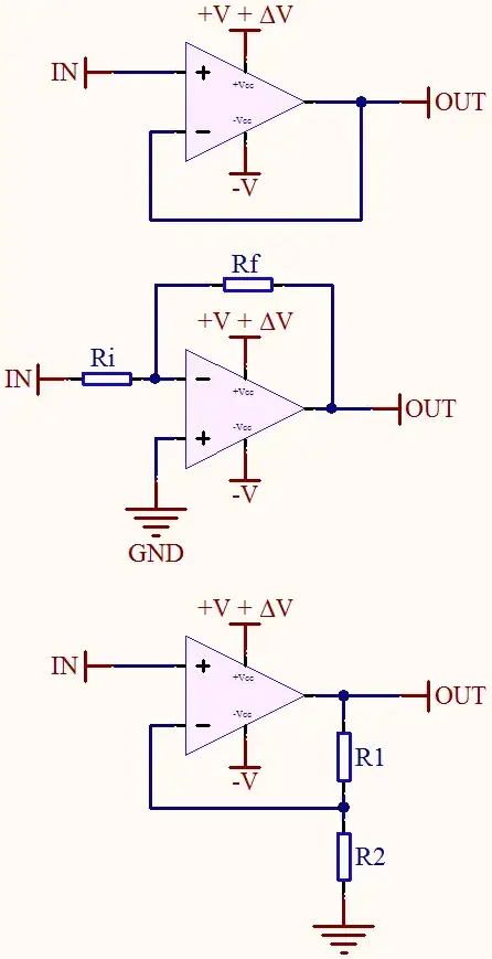
Suppose that, I'm designing a non-inverting amplifier with R1=100kO and R2=1kO. Supply voltages are; V+=+5.0V and V-=-4.5V. And my opamp is MCP6V31. What will be the output voltage, if my input voltage is 1kHz sinusoidal voltage, 10mV peak-to-peak?

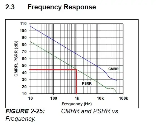
So, from the graph we'd expect about -90dB PSRR at 0Hz (DC), which would translate into about 3mV DC offset at output. For the stated input signal that will be hardly noticeable because the output will have an AC component of 1Vp-p. If you however drop the input signal to 10 microvolts p-p, the DC offset in the output caused by the rail imbalance will certainly be noticeable. Proof by LTspice.

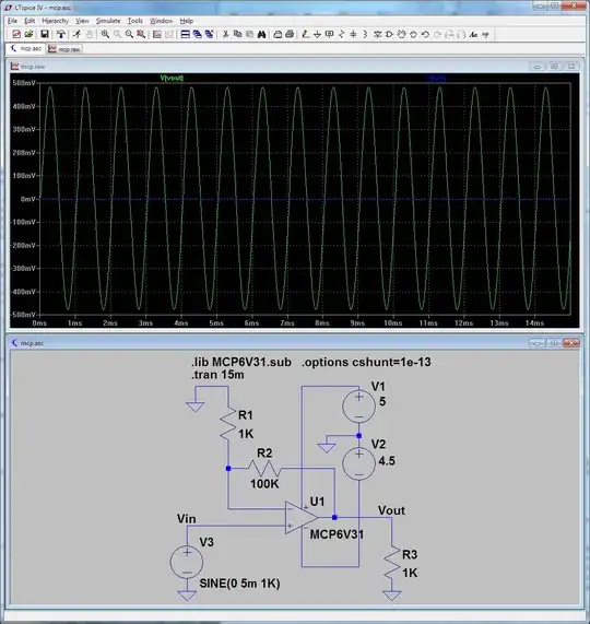
The question as asked: enter image description here

Now dropping the input signal to ten microvolts p-p.enter image description here

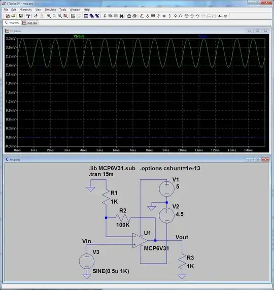
There's a visible DC offset at the output now. Just to convince you that it is caused mostly by the power supply imbalance, below is what happens if you use perfectly balanced rails at the same 10 microvolts input signal.enter image description here

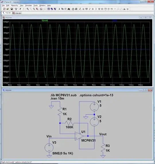
There is some offset here too caused by other non-ideal characteristics of the op-amp (input offset voltage, input bias currents), but it is much less than the one that was caused by the power rail imbalance.

Obviously you can also clip sooner on the negative rail if that is shifted up more significantly (given a large enough input signal). I'm not adding a graph for that as it's rather obvious.

Fizz
  • 14,355
  • 2
  • 43
  • 97
1

Rail asymmetries are hard to determine without knowing the internal topology of the op-amp. A lot of people think that an op-amp is an op-amp, but in reality there are many different implementations and technologies and trade-offs.

You won't get definitive answers (unless the designer is lurking here), but in general the asymmetry manifests itself in two ways. The first is the signal excursion, with the rail shifted the range of operation is also shifted, if you have a rail to rail op-amp and you move the rail then the signal will also move.

The second issue manifests itself in distortion products, often the internal circuitry has complementary functionality, one referenced to the upper rail and the other referenced to the lower rail and both with slightly different operating points, as the signal moves through different regimes of operation of the op-amp, different effect pop up and manifest themselves principally as distortion products (or slew rate differences).

To fully understand this you'd need to study the op-amp far more than you really need to.

Most of the constraints are embedded in the data-sheet. If you know what you are doing you can get hints as to the internal topology from that.

placeholder
  • 29,982
  • 10
  • 63
  • 110
1

If the power rails are moving up and down you can see how this affects the amplifier by looking at the graph of power supply rejection ratio (PSRR): -

enter image description here

I took this image from the data sheet and for a 1kHz signal superimposed on the power rail (positive or negative) there is 45dB of rejection. This means if 1Vp-p 1kHz is on a power rail, there is an equivalent voltage at the input of: -

\$V_{INPUT} = 10^{(\frac{-45}{20})} = 5.62mV_{P-P}\$

If your gain is unity then you'll see this voltage at the output. If your gain is 10 you'll see ten times this voltage.

EDIT Strictly speaking you should use the non-inverting gain to determine the power supply noise seen at the output of an op-amp. This means that for an inverting op-amp configuration with a gain of only 0.01, the power supply noise on the output is multiplied by 1.01 and not 0.01. A 1Vp-p 1kHz input voltage fed through an inverting amplifier with a gain of 0.01 will produce an output of 10mVp-p and if the PSRR at 1kHz is 45dB and there is 1kHz 1Vp-p on either power rail, there will still virtually be 5.62mVp-p of noise on the output and this is going to spoil the signal.

PSRR on wikipedia

Andy aka
  • 434,556
  • 28
  • 351
  • 777
  • 2
    IMHO, the OP means that the input signal is 1kHz, not the power supply noise. – johnfound Oct 17 '13 at 09:40
  • @johnfound The Op's input signal is 1kHz therefore it makes sense to state what the PSRR is at 1kHz! – Andy aka Oct 17 '13 at 10:25
  • 1
    No it doesn't. The noise in the power line very rarely has the same frequency characteristics as the signal on the input of the amplifier. To have in the power lines 50Hz or 30..40kHz is very common, while to have 1kHz is almost impossible. – johnfound Oct 17 '13 at 11:02
  • @johnfound The worst case scenario is when power noise IS the same frequency as the input - if this is 1kHz or 100kHz it doesn't matter - the answer I have given is an example. I might also point out that it is much more likely to see 100Hz than 50Hz (because that would be the ripple frequency from a bridge rectifier). I think you are splitting hairs now. – Andy aka Oct 17 '13 at 11:06
  • Well, you are only right about the 100Hz issue. :P – johnfound Oct 17 '13 at 11:08
  • @Andyaka What if the noise in power lines is low, but the power is asymmetric: -4.5V and +5V (instead of +-5V). Does this affect the integrity of the signal if I use it as a buffer and the input signal is +0.5 to +2.5V range? – Nazar Jul 28 '14 at 15:19
  • @Naz the only thing you need to watch out for is that the op-amp output doesn't get too close to the rails (you didn't mention gain) - on this example you could have a neg supply as low as a couple of volts but read the op-amps's data sheet on input common mode range - A lot of op-amps will work easily down to 0.5V on inputs and outputs so having gnd as neg rail would be OK. – Andy aka Jul 28 '14 at 16:24