3

I have a digital rheostat 10 kOhm potentiometer, that I want ultimately to control the volume of a radio, but for now, just want to fade an LED.

I have it fading in/ almost out, except I cannot make the LED turn of entirely.

I've been reading about the differences between rheostat and potentiometers - and many people mention different things, so I'm kind of confused. Also - i thought I ordered a digital potentiometer, but by accident bought a rheostat. soo.. is it even possible to make a rheostat "turn off" entirely?

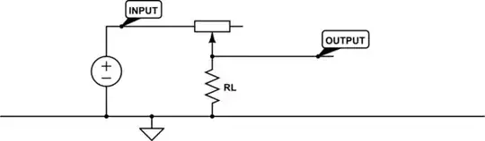
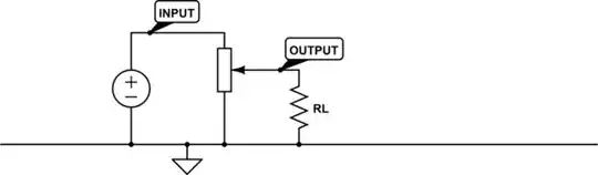
I have attached a schematic of the setup, and the code:

link to digi pot datasheet:

http://ww1.microchip.com/downloads/en/DeviceDoc/22060b.pdf

BREADBOARD: breadboard

SCHEMATICS: schematics

ARDUINO CODE:

#include <SPI.h>
int ss = 10; // slave select pins

void setup() {

 // set SS pin directions
 // Others are handled automatically

 pinMode(ss, OUTPUT);

 //Initialize SPI
 SPI.begin();

 Serial.begin(9600);

}
// function to set LED to specific level
// reg is the register, register is the index - this is only one pot,
// so the reg is == 00000000
// level is the leve

void setLed(int reg, int level) {

  digitalWrite(ss, LOW);  // set SS to low for communicating to that chip
  SPI.transfer(reg);      // send register / index
  SPI.transfer(level);
  digitalWrite(ss, HIGH); // Finish writing to that chip
}

void loop() {

 for(int i = 0; i<255; i++) {

   setLed(0, i);
   delay(20);

   Serial.println(i);
 }

 delay(500);

   for(int i = 255; i >= 0; i--) {

    setLed(0, i);
    delay(20);

    Serial.println(i);
   }
 delay(500);
}
jippie
  • 33,033
  • 16
  • 93
  • 160
Lasse Munk
  • 31
  • 2

2 Answers2

1

You can use the TCON feature to disconnect the wiper from the pot entirely. This should shut off the LED for you.

markrages
  • 19,905
  • 7
  • 59
  • 96
0

What you have is this

If I read the datasheet correctly though, your device misses the pin that is attached to ground and effectively all you can do is increase the series resistance for the load. You can increase it, but you cannot turn it entirely off.

schematic

simulate this circuit – Schematic created using CircuitLab


What you ultimately want to do is this:

If you connect the input to Vcc, you can control the output between 0V and Vcc. But your selected device misses the third pin that I connect to ground here.

schematic

simulate this circuit


How you can somewhat solve it

If you want to use this device and want to be able to entirely switch off the load, you'll have to bypass the load with an (electronic) switch like a transistor. Whenever you drive the transistor's base high through an I/O pin, it effectively shorts the output to ground, turning the load off.

schematic

simulate this circuit

Mind you that this works for DC, but not for and audio signal. For audio you need to change the circuit to work with small AC signals, but the idea is the same.

The R1 series resistor is included to protect both rheostat and transistor for excessive current when the rheo is near the top most position.

jippie
  • 33,033
  • 16
  • 93
  • 160
  • Maybe a MOSFET has better characteristics for audio, but the principle of shorting to ground is the same. – jippie Oct 07 '13 at 17:27
  • thank you so much for your answer. I am very new to electronics. Would you mind making the very nice looking schematics (that you've already made) for an audio circut? that would truly help me a lot! :) – Lasse Munk Oct 07 '13 at 17:31
  • I missed the TCON described in [Mark Rages](http://electronics.stackexchange.com/users/411/markrages) answer , that would probably be your better option for my "How you can somewhat solve it"-circuit. – jippie Oct 08 '13 at 05:25