3

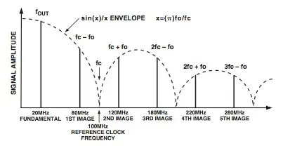
When looking at AD9850 DDS or other similar parts made by Analog Devices, it is obvious that the output signal amplitude changes with frequency. This can be shown as \$x= \pi \dfrac{f_{out}}{f_{clock}}\$ and amplitude changes by \$\dfrac{\sin x }{x}\$.

Using this formula, we should see an amplitude drop less that 20% between 1Hz to 50 MHz but this is not the case .

As I am driving this part, I see the amplitude is around 1 volt pk-pk at 10Hz and 10mV at 50 MHz. Am I missing something in these calculations?

enter image description here

JRE
  • 67,678
  • 8
  • 104
  • 179
Aug
  • 1,561
  • 6
  • 28
  • 63
  • 1
    I don't think that plot is showing what you think... It is telling you how to calculate the frequency and amplitude of extra spurious frequencies that will be generated when operating at certain fundamental and reference clock rates. It is not telling you how the amplitude of the fundamental varies as you change the fundamental frequency. – Justin Oct 02 '13 at 14:34
  • 2
    Yes, it is about aliased signals (images) and discusses about how to avoid them. But if we take the first part ( 0-100MHz),it is the fundamental frequency (0-50MHz) and the first image (50-fClock). – Aug Oct 02 '13 at 14:37
  • 2
    My guess is that you have too much capacitance (or a lower capacitance with a high series resistance) on the output. At 10Hz, the output has time to charge the capacitor before it changes polarity. At the higher frequency, the time constant exceeds the half-period and so the entire time is spent charging the capacitor, with the result that the voltage drops nearly to zero. – Scott Winder Oct 02 '13 at 14:38
  • This sinc-function trend of the output power vs. frequency is a mathematically predicted result of the fact that the DAC samples result in a series of *steps*, rather than of *impulses*. Generally, in a critical application these parts are followed by a limiter, though you could also try a compensating filter. – Chris Stratton Oct 02 '13 at 14:42
  • Ok, that's exactly I wanted to check. Is this problem related to my oscilloscope? ( it is an analog 50MHz and rather a cheap one ) or I should change my coupling capacitor to a smaller capacitance? – Aug Oct 02 '13 at 14:43
  • Is your capacitor part of a low-pass filter? Essentially by decoupling the output your are filtering out the higher frequencies. You need to calculate your desired roll-off frequency and design your filter to match. – Scott Winder Oct 02 '13 at 14:46
  • 1
    @ScottWinder - while Aug's circuit may be making the situation worse, please understand that this is an inherent property of this type of DDS, irrespective of loading. – Chris Stratton Oct 02 '13 at 14:48
  • no all the story is before or without low pass filtering. I am using a 100nF capacitor as a coupling capacitor just to remove the DC part so that I can see the smaller signals in higher frequencies with the oscilloscope. – Aug Oct 02 '13 at 14:50
  • @ChrisStratton Good to know. I wasn't aware that the amplitude decreased so much at higher frequencies. In that case, a limiter makes sense. – Scott Winder Oct 02 '13 at 14:51
  • 1
    Aug - is your scope probe 1x? Try switching to 10x as that will reduce the loading capacitance Scott is talking about. I don't think the step vs impulse rolloff predicts the degree of difference you are seeing. – Chris Stratton Oct 02 '13 at 14:55
  • @ScottWinder Theoretically this inherent amplitude drop should not be that much in the nominal working frequency (0-50MHz). It is obvious from the graph and calculations that it should be less the 20% – Aug Oct 02 '13 at 14:55
  • @ChrisStratton Yes it was on 1x. I will try 10x and will report the result here. – Aug Oct 02 '13 at 14:57
  • What is your reference frequency applied to the DDS circuit? – Andy aka Oct 02 '13 at 14:59
  • @Andyaka 125MHz – Aug Oct 02 '13 at 14:59

1 Answers1

4

In addition to the normal attenuation at increasing frequencies (as @ChrisStratton and OP pointed out), there is the potential to unwittingly add a low-pass filter to the output by decoupling it. This is based on the fact that the trace (or wire) between the DDS output and the decoupling capacitor will have some resistance, which combines with the capacitor to form an RC filter. The cutoff frequency is defined as: $$ f_{c}=\frac{1}{2 \pi RC} $$ Taking an arbitrary trace resistance of \$60 m\Omega\$ (consistant with a ½ inch, 8 mil, 0.5 oz trace) with your 100nF capacitor, we get: $$ f_{c}=\frac{1}{2 \pi \cdot 0.06 \cdot 100n} \approx 26.5MHz $$ This will change based on the actual resistance, as well as the capacitance of the scope probe (as discussed by @ChrisStratton), but it shows that the capacitance could be having a very real effect on the output amplitude at higher frequencies.

Scott Winder
  • 1,165
  • 7
  • 10
  • I never noticed the large impact of copper wire resistance. I reduced the distance between output and user part + reduced coupling capacitor to 50pF and also used 10x on oscilloscope. The amplitude is now as expected in the formula. – Aug Oct 02 '13 at 21:01