7

Assumption: I think it's generally true that commercially available AC/DC wall-worts can be expected to be pretty noisy (e.g. you can't count on much better than 5% stability).

Background: I'm dorking around with an RF application right now, and I hypothesize that some significant subset of my headaches is coming from powering my RF receiver with 5VDC coming directly from an AC/DC wall-wart (i.e. no RF choke, no regulator, nothing).

Question: What's the simplest way (e.g. fewest parts) and cheapest mechanism for converting the "angry" 5VDC off a wall-wort into a "happy" 5VDC for my RF receiver? I think the other subsystems are more tolerant to noisy power.

Aside: I wish I could give more definitive characterization of the noise coming out of the wall-wart, but sadly I am sans o-scope.

Edit1: In response to the request for more detail on parts being used:
vicatcu
  • 22,499
  • 13
  • 79
  • 155
  • 1
    the amount of time you might end up spending trying to figure out a noisy power supply might offset the cost of picking up an adjustable power supply, or even a decent single voltage Meanwell (or similar) 5VDC power supply. That said, maybe an LM6805 or LP2954 will do the trick? – Dave Dec 29 '10 at 15:27
  • @Dave i want to be able to take this "out of the lab" and put it in my living room though :) – vicatcu Dec 29 '10 at 15:29
  • What are the characteristics of your "headaches"? Can you give us a better idea of what parts you're using? – W5VO Dec 29 '10 at 15:47
  • @W5VO - I linked datasheets for the wall-wart and receiver I'm using. Headaches are basically terrible range performance when sourcing power from wall-wart – vicatcu Dec 29 '10 at 16:44
  • what input filter capacitor are you using? – markrages Dec 29 '10 at 18:07
  • 2
    That module will work down to 3.5V. So maybe you try putting an LDO regulator in and making 4.0V. – markrages Dec 29 '10 at 18:09
  • 1
    Have you put probes on your power line to see what your actually voltage is as well as the noise on it? An unregulated 5v supply isn't usually actually 5v after you hook it up. It would probably be good to actually see whats going on. I realize you don't have a scope, but a DMM is better then nothing. – Kellenjb Dec 29 '10 at 18:15
  • @Kellenjb yes, I've done that, DMM consistently reads between 4.75 and 5.25V. – vicatcu Dec 29 '10 at 19:04
  • @markrages, interesting thought on lowering operating voltage and using an LDO, might be worth a try - as for filtering caps; not using any right now (at least not upstream of the receiver), so I agree that is also something that's probably important to throw in. – vicatcu Dec 29 '10 at 19:06
  • @vicatcu 4.75 to 5.25 is a very large range, especially for a DMM to see. I wouldn't call that noise, in fact I am not sure what I would call it. Either way, I think you will be in a lot better shape by using a voltage regulator. – Kellenjb Dec 29 '10 at 20:32
  • Unregulated != noisy! A common transformer-rectifier wall-wart is actually impressively quiet, provided you don't have a lot of garbage on your AC lines. It'll have some 120 hz ripple (assuming full-wave rectification), but that's about it. – Connor Wolf Dec 30 '10 at 11:45
  • @Kellenjb, I actually mis-spoke on my DMM range. It's reads pretty stable (+/- 10mV)... I might be barking up the wrong tree thinking the power is my problem based on what I'm reading here :-/ – vicatcu Dec 30 '10 at 17:05

5 Answers5

6

The way to do this with the fewest parts - the only way to get 5Vdc from less than 5V - is to use a switching regulator. There are a few options, based on how much current you need. All of these can have inputs from ~1V-5.5V:

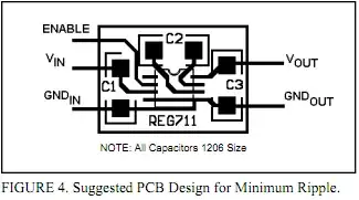
  1. TI REG711: 1MHz; 40mVpp ripple; 50mA; regulation not listed.
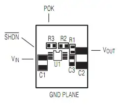
    REG711 layout
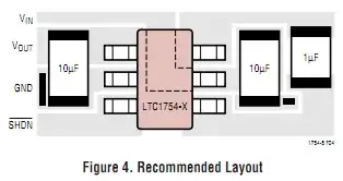
  2. Linear LTC1754: 600kHz; 65mVpp ripple; 50mA; 4% regulation. Linear LTC1754 layout
  3. Maxim MAX1759: 1.5MHz; 60mVpp ripple; 100mA; regulation not listed.
    alt text
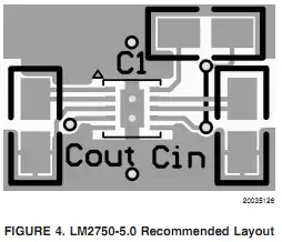
  4. National LM2750: 1.7MHz; 4mVpp-15mVpp ripple; 120mA; 4% regulation.
    alt text
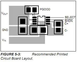
  5. Microchip MCP1252/1253: 650kHz/1MHz; 50mVpp ripple; 120mA; 2% regulation.
    alt text

There are others that will give 140mA and more, but the linked RF widget doesn't need it, these were pretty cheap, simple because they're just charge pumps, take up little space and are entirely surface mount due to the high switch frequency. Those with MHz switch frequencies are less likely to interfere with your 315MHz-434MHz project.

Easiest way to do it, in my opinion, is to get a different wall-wart!

tyblu
  • 8,167
  • 6
  • 40
  • 70
5

I have never had noise problems with wall warts, but then again, I never trust power supplies either and always add at least minimal filtering on my boards.

I usually add a 10 - 47uF electrolytic in parallel with a 0.1uF cap at the power inlet "just in case." This has never failed to clean up any ripple or spikiness from wallwarts.

Is the power supply regulated? Have you verified that the voltage is really 5V?

lyndon
  • 4,366
  • 1
  • 16
  • 11
  • I added a link to the datasheet for the wall-wart in the question. The datasheet *says* "Regulated output", but also says you can expect a 200mV Pk-Pk ripple (if you use 10uF + 0.1uF filter caps). – vicatcu Dec 29 '10 at 16:49
4

It's a switching wall wart. The easiest solution may be to just get a linear wall wart, or even just a transformer and regulate the voltage at your board. It's bulky, but 50/60Hz won't give you any RF problems.

Switching wall warts can be noisy, and there is little filtering you can do about it in terms of RF. All component filtering will do is filter conducted noise, not radiated, which is what could be your problem.

Also consider other sources of interference. I have an RF remote that won't work anywhere in my house when I run my dishwasher.

bt2
  • 3,784
  • 2
  • 25
  • 28
  • that's hilarious. I had a problem where TV channel 7 dropped out whenever the kitchen light was on. Then I realized that fluorescent tubes look like conducting rods when they're on, and they were close, and parallel to the rods of the antenna. Moved the antenna a little & problem solved. – Eric Nelson Sep 02 '18 at 05:31
2

An an alternative, turn an ATX power supply from an old computer into a benchtop power supply. I can't speak for how clean the power is (I imagine quite good) but it's a cool project!

Isaac
  • 296
  • 1
  • 3
0

Simple, cheap and most cleanest solution:

Use lm7805/LM2941/LP2985/ any other linear regulator, low-drop are better.

There are many ultra low drop LDO that even don't need to adjust source voltage if it is already 5.2-5.3v. In other case adjust voltage to 5.5-7v according to linear regulator requirements. To adjust voltage change zener inside AC-DC circuit.

Most of cheap "power usb adapter"s from China can be converted in this way.

user1329019
  • 21
  • 1
  • 4
  • 1
    I've taken apart of few wall-warts and although they sometimes have discrete Zeners, these tend to be for bootstrap powering a switching regulator chip. They don't regulate the actual output power, so changing the Zener won't change the output voltage. Also, many have the Zener for the bootstrap power in the switching chip itself, which prevents you from changing it anyway. – Math Keeps Me Busy Jul 24 '21 at 23:26