6

I need help with a project. I want to make a circuit to work as a night-time motion detector circuit that will power several LEDs. I bought:

  • 1 LDR
  • some NPN transistors BC547 and 2N3904
  • some resistors 100kOhm
  • boost regulator 3V to 5V
  • PIR sensor

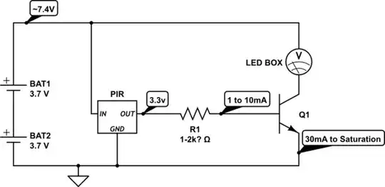
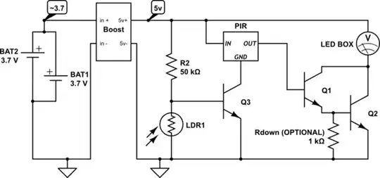
I connected the LDR to 2 NPN BC547 transistors and successfully tested it. Then I connected the (-) from NPN transistor to the (-) of the PIR and the (+) of the PIR to (+) and the output of the PIR to a single led. It worked but the LED had a low output.

If I connect the PIR output to a 2N3904 transistor and after to the LED, the LED is brighter. But when I connect the current to the voltage booster and to all LEDs, the light is very low.

The problem is the 3.3V from the PIR output. I need 5V to work my LEDs. How can I establish this?

Update: This is my PIR Sensor (mod edit: Pretty much a standard BISS0001 Design, no transistor on the output.)

enter image description here

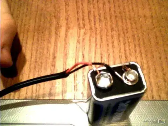
My Power Supply Is 2 Batteries 3.7V 18650

Passerby
  • 72,580
  • 7
  • 90
  • 202
  • Kudos, @Dave, you cleaned this up rather well. – JYelton Oct 01 '13 at 20:32
  • A schematic of how you have everything hooked up is crucial for us to be able to help you. – Passerby Oct 01 '13 at 20:50
  • How much power can you get from your PIR output? – Andy aka Oct 02 '13 at 07:30
  • PIR = Passive Infrared sensor? – AKR Oct 02 '13 at 12:14
  • Some questions. What are the NPN's doing? (a schematic will probably answer this as Passerby requested). What sort of PIR are you using? (a raw sensor or a module with buffered outputs?). Ive used both and the raw sensor needed a capacitor to connect to the sensing circuit to make it change sensertive and not level sensertive. – Spoon Oct 02 '13 at 12:38
  • What is your power supply? 3.3v out the PIR into the base of a transistor switching 5v to an LED gets it done. We need a schematic. – mikeY Oct 02 '13 at 15:24
  • OK... it's a module of some sort .... Is there a link to what it's supposed to be ?.. or even a high resolution picture of the PCB? – Spoon Oct 02 '13 at 18:35
  • dear friend all these will be in a solar led light. i have the light but i remove all from inside to make it as i want! – panayiotis kasapis Oct 02 '13 at 18:55
  • @panayiotiskasapis there is a free schematic editor that you can use. Edit your post and hit ctrl-m on your keyboard to bring it up. – Passerby Oct 02 '13 at 20:07
  • @spoon I edited the post. The PIR module is a fairly standard BIS00001. – Passerby Oct 02 '13 at 20:07

1 Answers1

5

A boost regulator is not useful here. The problem is that your module, based on the BISS0001 PIR IC, the output pin is VCC (3.3v) 10mA max. Connecting a boost regulator to this output would be really limited.

All you need is a single transistor.

schematic

simulate this circuit – Schematic created using CircuitLab

Problem is that you need a transistor that works on the current provided from the output pin. Normally you see a 1k or 2.2k resistor on the board from Pin 2 of the BISS00001 to the output pin, which means only 2ma or 1.2ma at the output pin.

So you need either 1) a Transistor with a HIGH HFE or 2) a Darlington Pair (Two transistors in a pair).

schematic

simulate this circuit

These numbers are all based on the transistor you choose. A 2n3904 is only 100mA to 200mA max, with a hfe of 30 (So it multiples the base current, 1mA by 30, and that's the maximum current you get at the collector, 30mA).

You need to know how much current your led box needs, and what voltage it can use. I also assumed that your two batteries are in series.

See this page http://www.electrobob.com/fun-with-leds/ for a project that does both LDR and PIR for leds (but not the same way as what I think you want).

Adding the LDR as a night time detector is simple, and also requires a transistor.

schematic

simulate this circuit

Q1 and Q3 can be any weak small signal transistor (2n3904 100mA), Q2 should be a better one depending on your led box current needs (2n2222 1Amp). Adjust R2 for sensitivity.

Passerby
  • 72,580
  • 7
  • 90
  • 202
  • DEAR FRIEND THANK YOU FOR THE ANSWERS AND HELP.MY BATTERIES ARE PARALLEL. TOTAL VOLTAGE OUTPUT WHEN CHARGED 4.2V NOW THE LAST CIRCUIT THAT YOU MAKE FOR ME IT WILL WORK? IF YES SO I NEED TO BUY TRANSISTORS 2N2222. AM I CORRECT? THANKS – panayiotis kasapis Oct 03 '13 at 10:02
  • ALSO THE RESISTORS YOU SHOW IN THE CIRCUIT ARE THESE I HAVE 100K Ohms OR SOMETHING ELSE??? THANKS – panayiotis kasapis Oct 03 '13 at 15:22
  • In that case, the batteries in parallel should connect to the Booster circuit you have, and everything should connect to the 5v side of the booster. R2 can be 100k, r1 is inside of the PIR module already, and Rdown is optional, so if you dont have it don't worry. And Yes, a 2n2222 or similar, any transistor that can handle 1 AMP should be fine. @panayiotiskasapis – Passerby Oct 03 '13 at 19:02
  • woooo i did not get it! as i know ( not much) the boost i must connect it to the pir output so the 3.3v make them 5v but it does not because as i understand from you i have low (ma). i try that several times. or if you mean i connect the boost from the beggining of the circuit after the batteries , when there is an output from the pir it is going to be 3.3v again? or more? please drawn it for me if you can i am confused now – panayiotis kasapis Oct 03 '13 at 19:08
  • @panayiotiskasapis updated the circuit. The PIR has it's own regulator, and works on 3.3v, so yes, the output is still 3.3v so the transistors are still required. – Passerby Oct 03 '13 at 19:20
  • thanks sir! just to see if i understand well i am watching the circuit you make me! i have already connect the ldr with 2 bc547 transistors.you show me 1 in the circuit. does it matters? also + of the ldr goes directly to + and not with resistance. the resistance leave from the other side of the ldr and goes to the base of the npn transistor as i show to the first drawn i make please see it again! to make the circuit you present it i must order other ldr to test it because as you can see in my pictures i rush and i put a lot of glue :P – panayiotis kasapis Oct 03 '13 at 20:15
  • i also order from ebay 2n2222 transistors as you told me i need to use 1. so what can i do now, i connect the boost as you told me , and if you tell me that the ldr is ok as i make it, i must connect 1 transistor 2n3904 and 1 2n2222 as you show me to the circuit from the pir output and it will work? – panayiotis kasapis Oct 03 '13 at 20:20
  • @panayiotiskasapis putting the ldr as the top resistor makes the circuit turn on during the day, off during the night. By putting it on the bottom with the weak pull up, it turns on at night. If the PIR module needs more current, yes a second transistor might be needed. And LDRs can be connected either way, just like resistors, they don't have polarity. Both sides act the same. – Passerby Oct 03 '13 at 21:13
  • dear friend so i can leave the ldr and pir circuit as i make it correct? and after that i must connect 1 transistor 2n3904 and 1 2n2222 as you show me to the circuit from the pir output and it will work? – panayiotis kasapis Oct 04 '13 at 06:19
  • @panayiotiskasapis yes, it should. – Passerby Oct 04 '13 at 06:25
  • ok sir thanks i wait for the transistor to come and i will informed you. thanks! i think it will take about 3 weeks to arrive! – panayiotis kasapis Oct 04 '13 at 09:35
  • let us [continue this discussion in chat](http://chat.stackexchange.com/rooms/10888/discussion-between-panayiotis-kasapis-and-passerby) – panayiotis kasapis Oct 04 '13 at 13:12
  • dear friends sorry for long time to answer. i connect the npn transistors together to the circuit and the power is much more but not as much as i need.i did not use the boost because it gives me the same result , as the reason of the pir output 3.2v. – panayiotis kasapis Feb 22 '14 at 10:59
  • so here i go again. i connect the ldr , the npn transistors and the pir as i show in my fist picture i drawn. this give me the correct idea to have output voltage the night when it take a motion. as here good. then thanks to your help i connect from the pir output the 2 npn 2222 transistors and i have more voltage.the leds turn on but not in full power. it is like i have low voltage batteries but they are not – panayiotis kasapis Feb 22 '14 at 11:08
  • i enter a drawn i make to show how i follow your informations. waiting your reply.(note that my batteries when charge output 4.2v not 3.7v) thanks – panayiotis kasapis Feb 22 '14 at 11:27
  • i hope you see my answers – panayiotis kasapis Feb 23 '14 at 11:07