The analogue MUX that you are using is limited to passing signals that have voltage ranges that vary between VEE and VDD. In your schematic the operational signal range is from 0 to 3.3V. If your TOS Link signals are outside that range you will need to re-think your design.
Another thing to keep in mind is that the MUX you are using may be limiting the bandwidth of the signal that you are trying to pass through it. The data sheet shows propagation delays through the part from 5 nsec to 30 nsec. Since the signal has to change state twice to make it through the part these delays correspond to a frequency range of 1.5MHz to 10MHz. If you observe in the data sheet the part gets quite a bit faster at VDD equal to a higher value. The delays shown in the data sheet start at 5V and go up to 15V. The 3.3V level you are using is not even shown and the part will be even slower at this voltage. This bandwidth thing is important to consider when selecting a proper MUX for your TOSLink signals. If the link is faster than the propagation through the part you will have troubles getting the '4051 to work as designed.
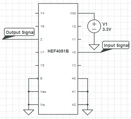
This MUX part is a bi-directional part. You can use either the Y or the Z pins as the input.
These MUX parts also have a fairly high ON resistace which you can see in the data sheet. This resistance varies according to the applied VDD voltage on the part. You need to look carefully at the circuit that drives and receives the TOSlink signals on either side of the MUX. The ON switch resistance ends up in series with the signal line and could be too high of resistance to allow your circuit to work. Look in your circuit for low value pullup/pulldown resistors at the TOSLink receivers, series resistance designed into the circuit at the TOSlink driver or higher current levels passing between the TOSLink driver and the receiver. The switch resistance could be causing signal level integrity problems taking these factors into account.
The best way to try to evaluate the real functional behavior of your circuit will come when you hookup an oscillocope and look at the waveforms of your circuit.