3

Reading questions on converting negative voltages to positive ones it has left me with a question that I can't seem to work out. The circuit looks like this:
Op Amp Adder

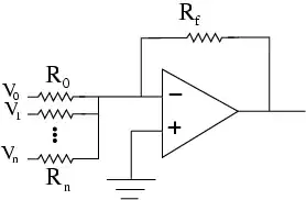
But you only have the one going to the inverting input. My question is:

When inputting a positive voltage it doesn't change/very slightly change. So do you have to implement something else for when the voltage is positive?

EDIT: Image borrowed from Kortuk's answer here

                                R
                               ___
                       .------|___|----.
                       |               |
                       |               |
                       |               |
                       |        VCC    |
                       |         +     |
          R            |         |     |
         ___           |       |\|     |
 Input -|___|----------o-------|-\     |   Output
                               |  >----o----
                        .------|+/
                        |      |/|
                        |        |
                       ===      ===
                       GND      GND
Dean
  • 8,408
  • 27
  • 70
  • 120

2 Answers2

10

This circuit will not work with the negative supply pin connected to ground. It is an inverting circuit, which causes the input voltage to be "mirrored" around the + input, in this case 0V.

But the opamp's output cannot go beyond the supply rails, which are at 0V and +9V.

To fix this you can connect the + input to 4.5V instead of 0V. (This assumes Rf is equal to R0..Rn) One way to accomplish this is a voltage divider, equal resistors to +9V and ground.

markrages
  • 19,905
  • 7
  • 59
  • 96
5

Your first image has an implicit positive and negative power supply, which allows the output to swing above and below the reference voltage (ground). If you assume an ideal op-amp (usually reasonable for these circuits), then the inverting output is a virtual ground - it is driven to the same voltage as the non-inverting input. The current through the feedback resistor (Rf) must be equal to the sum of the currents flowing through the input resistors (R0, R1, Rn...).

\$ \dfrac{V_0 - V_{ref}}{R_0} + \dfrac{V_1 - V_{ref}}{R_1} + \dfrac{V_2 - V_{ref}}{R_2} = \dfrac{V_{ref} - V_{out}}{R_f} \$

To make the math easy, lets make Rin=R0=R1=R2. The output voltage becomes:

\$ V_{out} = \dfrac{-R_f (V_0 + V_1 + V_2 - 3 \cdot V_{ref})}{R_{in}} + V_{ref} \$

In the first example, Vref=Ground=0V, which simplifies the equations a bit. If (V0+V1+V2) > 0, then Vout will be negative. If Vout can't be negative, due to a lack of a negative rail or negative voltage headroom, then the circuit stops functioning as intended.

Nothing explicity requires you to have a negative rail, and single-supply operation is usually desirable for its simplicity. In order to get the expected signal swing, you need to set Vref to some value between VDD and Ground. A pair of resistors acting as a voltage divider will work, or a poteniometer would allow you to adjust the reference voltage.

In the context of this question, the object was to measure voltages that were always below your ground reference, without having a negative power supply. In that case, a reference voltage of 0 would be OK because the output voltage would never need to swing below the negative rail.

W5VO
  • 18,303
  • 7
  • 63
  • 94