0

I built this quick test circuit before I start implementing a switch with multiple receivers and it isn't working correctly. The transmitter appears to be working (I can see the red light on) but when I connect my stereo receiver to the transmitter and my DVR to the receiver I get no sound (tested both cables and they are not the fault).

PLR135/T10 Receiver Datasheet. PLT133/T6A Transmitter Datasheet

enter image description here

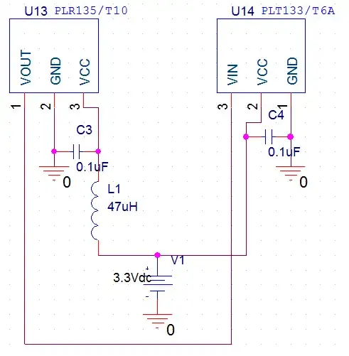
My only worry is that Pin 1 has swapped locations between the receiver and transmitter even though the manufacturer is the same. I double checked the datasheets and I believe my schematic is correct with the swapped Pin 1 locations.

Passerby
  • 72,580
  • 7
  • 90
  • 202
user2665581
  • 129
  • 14
  • 1
    When facing the front of it, the pins of the transmitter are Vin, VCC, Gnd, and the Receiver is VCC, Gnd, Vout. Is this how you have it set up? – Passerby Sep 30 '13 at 00:43
  • @Passerby This is what I have when looking at the front--from left to right on transmitter: Vin, VCC, GND. From left to right on receiver: Vout, GND, VCC – user2665581 Sep 30 '13 at 01:37
  • I don't know if this is what's going on, but the C3/L1 filter looks fishy. This filter has an anti-resonance around 73 kHz that could certainly mess things up. Maybe use a ferrite instead of the inductor, and/or add a larger-valued cap (1 or 10 uF) in parallel with C3, and/or design in some loss in the filter (a small R parallel with L1 or series with C3). – The Photon Sep 30 '13 at 02:37
  • 1
    @ThePhoton they are using the values defined in the datasheet. – Passerby Sep 30 '13 at 04:33
  • @Passerby, what datasheet? – The Photon Sep 30 '13 at 04:37
  • @ThePhoton you can find the two datasheets by googling the part numbers in the schematic – user2665581 Sep 30 '13 at 04:41
  • @user2665581, it's much better if you add a link in the question for the datasheets of the parts you are using. For example, if two different companies had parts with the same part number, it might not be clear which one you are using. – The Photon Sep 30 '13 at 04:45
  • 1
    Next question: What type of TOSLink are you using. I'm not strictly familiar with TOSLink, but Wikipedia (and a Toshiba datasheet) indicate TOSLInk could involve data rates up to 125 Mb/s. While the Everbright datasheet for your part number says it's only usable up to 16 Mb/s. The Everbright part might be usable with legacy TOSLink, but not with the latest-and-greatest high-speed version. Do you know for sure which version your DVR has? – The Photon Sep 30 '13 at 04:47
  • I could not find the information for my DVR but I also tried it on my desktop sound card and it didn't work also. I'm using an asus xonar dg and this is what it says in the manual: S/PDIF Digital Output: 44.1K/48K/96KHz @ 16/24bit Dolby Digital, DTS, WMA-Pro http://dlcdnet.asus.com/pub/ASUS/Audio_Card/Xonar_DG/E7802_Xonar_DG.pdf – user2665581 Sep 30 '13 at 05:25

2 Answers2

0

Try this. Put a cable between the transceiver and the receiver. Then connect a spdt switch to the transceiver's vin. The other two ends of the switch go to vcc and ground. Flip the switch, make sure the transmitter led is turning on, and then use a multimeter to test the vout pin on the receiver.

schematic

simulate this circuit – Schematic created using CircuitLab

This will tell you if the two are working. Even better, a very slow clock that you can measure would work as well. A 555 chip set up for 2hz connected to vin should cause vout to switch on and off two times a second (See: https://electronics.stackexchange.com/a/64527/17178)

Passerby
  • 72,580
  • 7
  • 90
  • 202
0

Figured out the problem. Vout and Vcc were backwards for the receiver--datasheet must be wrong or their way of showing the pinouts is wrong. Sound is coming out and working perfectly now

user2665581
  • 129
  • 14