2

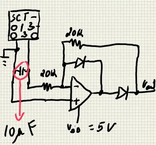
I'm actually trying to build a precise full wave rectifier. But after a first failed try, I though I would better be off break down things to analyse every part of the circuit.

So, I started building a half-wave rectifier...

enter image description here

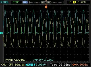
and even at this point I'm seeing something I was not expected:

Precise half-wave rectification

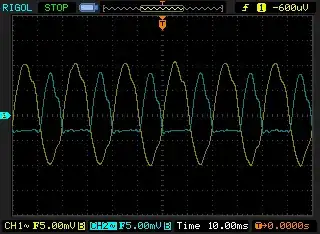
So, has you might guess, the yellow wave-form is my Vin and the blue is my Vout (both channels are AC coupled).

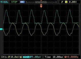
Here's the difference when I change my scope settings to have both channels to DC coupled:

DC coupled

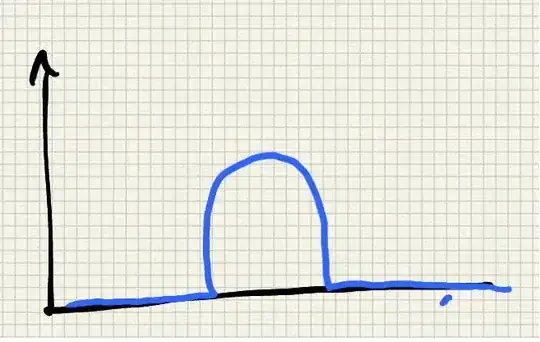
I was sincerely expecting to get something more like this:

expected

Currently I'm using 20k (1%) resistors, ahottky diodes (1N5818) and the TLC272ACP op-amp.

Any thoughts on what is going on? Why am I still getting a negative portion of the rectified wave form? I must have messed something up...


I've basically edited this post, because I realized that I've made a mistake on the circuit. As I'm using this circuit to power up an A/C appliance, I wanted to use the same power supply to power up the circuit. So basically I've connected a AC/AC transformer to drop-down voltage from 230 to 6V (or 12V), and then got the AC converted to DC through a bridge rectifier and later regulated to 5V.

The thing is, I noticed I was using "different grounds" in different parts of my circuit. I was giving ground passed through the voltage regulator to the op-amp and giving ground directly out of the bridge rectifier to the bias the CT sensor.

For some reason that is not clear to me, between the "regulated ground" and the ground output directly from the bridge rectifier there's a difference of 2.3mV.

Well, know after having this corrected I get this on the scope:

Same ground...

Once again, I was expecting a closer match in terms of Max voltage...


cvicente
  • 131
  • 3
  • 10
  • What does the circuit look like? – jippie Sep 21 '13 at 17:59
  • Check http://electronics.stackexchange.com/a/82619/8627 and http://electronics.stackexchange.com/questions/82615/no-germanium-diode-available-for-small-crystal-radio-can-active-components-ha/82619#comment162031_82615 – jippie Sep 21 '13 at 18:00
  • 5
    I'm not familiar with your scope, but I suspect from the labels that your scope inputs are AC-coupled, which would account for the output waveform going negative. – Peter Bennett Sep 21 '13 at 18:04
  • @jippie Like a typical [text-book precise half-wave rectifier (the improved version)](http://en.wikipedia.org/wiki/Precision_rectifier) – cvicente Sep 21 '13 at 18:12
  • 1
    @PeterBennett I just bought the Rigol 1052E, and I've never worked with an scope in my life, basically I read some tutorials but I'm not completely familiarized with it. So... do you mind explaining what exactly do you mean by your answer? (sorry... extreme noob here). – cvicente Sep 21 '13 at 18:21
  • @jippie Thank you for the links! I've read them through, and it appears to me that I should probably start by applying a dual power supply right? – cvicente Sep 21 '13 at 18:23
  • @cvicente Peter Bennet means that the little squiggle shape after "CH1" or "CH2" on your scope picture implies you scope measurement is blocking DC levels and hence the waveform will drop down so that the area under the centre horizontal line = the area above it and hence your "blocked" half is a few millivolts down but realistically you can't expect an answer without a circuit being posted. – Andy aka Sep 21 '13 at 18:36
  • 2
    @cvicente: There should be a setting for each input channel to select AC coupling, DC coupling, or Ground. With AC coupling, there will be a capacitor inserted in series with the input to remove the DC component of the signal. DC coupling removes this capacitor. If your signal was a square wave going from 0V (ground) to +2V, DC coupling would show it correctly, but AC coupling would show it going from -1V to +1V. – Peter Bennett Sep 21 '13 at 18:44
  • Necessity for a dual power supply really depends on your circuit diagram. You should include that in your question. – jippie Sep 21 '13 at 19:58
  • I've just edited my question to include the circuit diagram. – cvicente Sep 22 '13 at 14:12
  • edit: CT has built-in burden resistor: http://www.ghielectronics.com/downloads/Gadgeteer/Module/SCT013-030V%5B1%5D.pdf Is that 10 uF capacitor polarized? Because that would also distort the waveform. – markrages Sep 22 '13 at 15:01
  • @markrages Yes it is! I was trying to smooth out some spikes... but I'll remove it... – cvicente Sep 22 '13 at 16:13

1 Answers1

1

It looks like your output is only going about 4mV below ground. The input offset voltage for the TLC272 is up to 10mV so maybe you need to pick an opamp with a smaller offset. Seeing a schematic would be helpful, too.

Joe Hass
  • 8,447
  • 1
  • 29
  • 41
  • The schematics is the one of a [text-book precise half-wave rectifier](http://en.wikipedia.org/wiki/Precision_rectifier) – cvicente Sep 21 '13 at 18:03
  • 1
    @cvicente linking to a text book circuit does not give values. I'm interested in the values you have chosen, what frequency you are inputting and what gain you have. Maybe you can post your exact circuit. – Andy aka Sep 21 '13 at 18:27
  • I've just edited my question to include the circuit diagram as requested. – cvicente Sep 22 '13 at 14:25
  • I've also corrected the OP-AMP... I forgot the ACP at the end, so it's TLC272ACP. – cvicente Sep 22 '13 at 14:32
  • I think Peter Bennett may have hit the nail on the head with his observation that the 'scope is ac coupled. It is critical that you fix that problem and let us know how it affects your waveforms. – Joe Hass Sep 22 '13 at 16:29
  • @JoeHass But I can change the settings to be DC coupled o ground. I've tried DC, and the wave form of Vout is basically shifted up (in terms o mV). With ground I just get a flat line. – cvicente Sep 22 '13 at 21:01
  • Does the waveform match your expectations when you use the dc setting? The "ground" setting just grounds the input so you can see where 0V would be on the screen. – Joe Hass Sep 22 '13 at 21:27
  • @JoeHass Not at all Joe. The wave does shifts up... but unfortunately way to much. The bottom part of the waveform, that in question screenshot is below ground, when I use DC coupled it shifts way above the ground. It would be great that I could post a screenshot in the comments... – cvicente Sep 22 '13 at 21:41
  • You should be able to edit your own question and add a new screenshot at the bottom, with a brief explanation that you changed the input coupling of the signals. – Joe Hass Sep 22 '13 at 21:45
  • let us [continue this discussion in chat](http://chat.stackexchange.com/rooms/10701/discussion-between-cvicente-and-joe-hass) – cvicente Sep 22 '13 at 21:55
  • @JoeHass I've added a screenshot with the waveform differences when I change the scope settings from AC to DC coupled. – cvicente Sep 22 '13 at 22:32