0

I've been searching for a circuit that has a centralized switch, with 4 different switches for separate groups of LEDs.. and all I get for a result are diagrams without a centralized switch.

Well, to elaborate what I'm talking about, here it is:

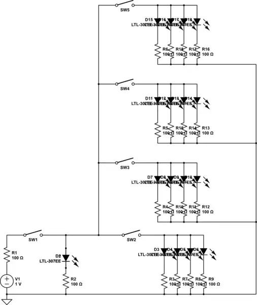
I'm looking for a schematic that has an on/off switch for the main LED. When the main switch is turned on, the main LED is switched on, and (say we have 4 different switches connected to it, with 4 LEDs connected to one switch) I can pick which group of LEDs I want to light up, hence the different switches. And when all the switches are switched on, all LEDs will light up.

When the main switch is turned off, all the LEDs will be turned off too.

Chetan Bhargava
  • 4,612
  • 5
  • 27
  • 40
  • 1
    I am a bit confused; if the main switch is ON, and 3 out of 4 secondary switches are ON, only the MAIN LED will be on (for example?), but if the MAIN is ON, and ALL 4 secondary are ON, then we will see 17 LEDs on? – KingsInnerSoul Sep 19 '13 at 13:52
  • Do you think you could sketch out what exactly you mean? The textual description you have given is somewhere between confusing and incomprehensible. If you do not have enough reputation to add an image into your question, please upload the sketch to any publicly accessible image hosting site, such as imgur.com, post the link as a comment here, and someone will incorporate the sketch into your question for you. – Anindo Ghosh Sep 19 '13 at 14:03
  • 1
    Main switch, switched on [Main LED lights up] = switches (1) (2) (3) (4) can be enabled all at the same time, or switch (1) only or any combination between the 4 switches. Main switch, switched off [Main LED turned off] = all LEDs [switches] automatically turned off. – Cha Talplacido Sep 19 '13 at 14:40

2 Answers2

2

If I understand your question correctly, then this should work.

schematic

simulate this circuit – Schematic created using CircuitLab

Values are default. Its up to you to find the right values for each element.

KingsInnerSoul
  • 829
  • 14
  • 29
  • I was not aware of the schematic editor option. I removed the image, and added the schematic. – KingsInnerSoul Sep 19 '13 at 14:56
  • R1 should be removed, otherwise groups of LEDs will change brightness as other groups are switched on and off. Also, the combinations of 4 LEDs in parallel with a single current-limiting resistor is not a good idea. Unless they are very precisely matched, they will not light evenly. – Tut Sep 19 '13 at 15:17
  • Wait, I forgot to say that the LEDs we will use wouldn't be of the same brightness.. we're really aiming for that. First switch will be the brightest, the second will be dimmer and so on – Cha Talplacido Sep 19 '13 at 15:35
  • See [why-exactly-cant-a-single-resistor-be-used-for-many-parallel-leds](http://electronics.stackexchange.com/questions/22291/why-exactly-cant-a-single-resistor-be-used-for-many-parallel-leds) – Tut Sep 23 '13 at 15:27
1

Put the main switch in series with everything else and it will work as a master switch, which it seems is what you are asking about.

Olin Lathrop
  • 310,974
  • 36
  • 428
  • 915
  • Main switch, switched on [Main LED lights up] = switches (1) (2) (3) (4) can be enabled all at the same time, or switch (1) only or any combination between the 4 switches. Main switch, switched off [Main LED turned off] = all LEDs [switches] automatically turned off. Like the diagram below? – Cha Talplacido Sep 19 '13 at 14:47