Why do they tell that
• Burst length should be 10 cycles/burst or longer. After each burst which is between 10 cycles and 70 cycles a gap time of at least 14 cycles is necessary
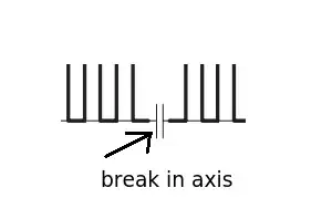
whereas I see only 7 in the 600us bursts of their time diagram
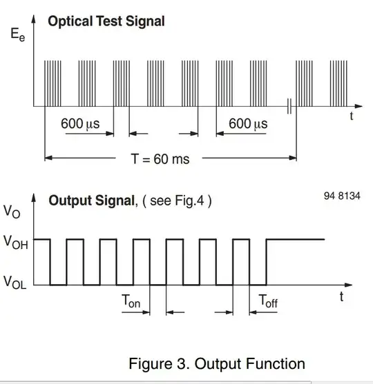
And what is the "carrier frequency" (30kHz)? I think infrared light frequency is measured in terahertz? Are those 7 pulses in the 600us bursts in the diagram are periods when LED emits light with gaps imbetween? How actually I supposed to communicate over the carrier frequency?
Why do they tell that 30 pulses, f = 30 kHz, T = 10 ms in the following Figure 1
My computation is that if every pulse takes 1/30k sec then 30 pulses take T = 1 ms. Furthermore, I see on this diagram that reception terminates (V_O goes high) even though transmitter is still bubbling. Can it predict the future?
update Also, the upper part of the second diagram (Figure 1) says that 10 led pulses is optimal for reception but bottom clarifies that receiver recognizes the burst that is between 7 and 15 LED pulses. That is, it is guaraneteed to receive bursts only when they are 15 LED pulses or longer. How can I use the optimal 10-pulse bursts then?