3

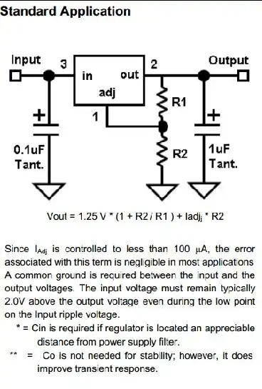
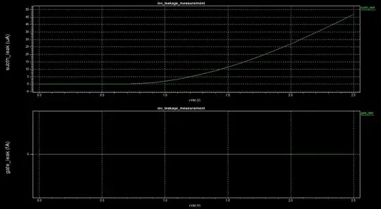
I would like to measure the leakage current of a CMOS inverter. As this current depends on the input, I decided to measure something average, namely, the leakage current of a ring with two CMOS inverters so that both PMOS and NMOS devices have an opportunity to be in both on and off states. I am using a SPICE simulator for this purpose. My circuit is as follows (not-that-relevant instructions are omitted):

X1 in  int dd ss bn bp inverter
X2 int in  dd ss bn bp inverter

Vdd dd 0 1
Vbp bp 0 1
Vbn bn 0 0
Vss ss 0 0

.ic V(in) = 0
.probe dc Ileak = par('abs(I(Vdd)) / 2')

where inverter is a subcircuit based on BSIM4 (v4.7) devices.

Since I have little experience in this area, I cannot really tell if what I am doing makes sense. I would be grateful if somebody could confirm that the circuit serves the desired purpose.

There is one more aspect that I would like to clarify. My global target is to get a rough estimate of the leakage current of a larger circuit based on the measurements of this little ring. I understand that this estimate will probably be (very very very) vague and abstract. Nevertheless, such an approach is good enough for me. However, I would like to push this estimate as far as I can, and I am wondering if it would be better to include some loads in the circuit between the two inverters as shown below:

.subckt load in dd ss bn bp
X1 in  int dd ss bn bp inverter M = 3
X2 int out dd ss bn bp inverter M = 12
.ends

X1   in int dd ss bn bp inverter
X1_1 int dd ss bn bp load

X2   int in dd ss bn bp inverter
X2_1 in dd ss bn bp load

Vdd dd 0 1
Vbp bp 0 1
Vbn bn 0 0
Vss ss 0 0

.ic V(in) = 0
.probe dc Ileak = par('abs(I(Vdd)) / 2')

where load is a subcircuit with a couple of slightly enlarged inverters.

Ivan
  • 209
  • 3
  • 8
  • 1
    I suspect that you are confusing terms here. Could you clarify what you mean by leakage current? The circuit will _consume_ current, principally during switching. True leakage current (gate oxide), S/d b-b tunnelling etc. is not modelled in SPICE, and in particular SPICE is known to not be charge balanced. However, some people may have tried to fit leakage into their SPICE models so there may be particular instances here where I am wrong, – placeholder Sep 14 '13 at 12:00
  • @rawbrawb, thank you for the response. I am mostly referring to the two main contributors to the static dissipation of power, namely, to the subthreshold and gate leakage currents. Both are taken into account in the [BSIM4](http://www-device.eecs.berkeley.edu/bsim/Files/BSIM4/BSIM470/BSIM470_Manual.pdf) model of MOSFET devices. – Ivan Sep 14 '13 at 12:20
  • Since you are running a dc simulation I don't think the presence of a load will make a difference in the gate or subthreshold leakage, but the way you have set up the simulation your average current will include the current leakage in the load itself and I don't think that's what you want. You may have to use initial conditions to get the ring out of metastability. – Joe Hass Sep 14 '13 at 13:24
  • IF you're completely sure that your model does model the gate leakage accurately then measuring this current is not a big issue: just integrate the current at the gate terminal of the inverter. The total value of this integral is the current which flew into the gate but did not return. However, you must apply some initial and boundary conditions to this measurements. I'll be able to post a more elaborate answer once you describe what exactly do you mean by Subthreshold current, in particular: in what conditions do you treat the current as subthreshold. – Vasiliy Sep 14 '13 at 14:24
  • @JoeHass, yes, I agree that, in the second case, the measurements will also include the current through the load, and it is indeed not what I want. Thank you for the note. Regarding the initial condition, if I am not mistaken, you are referring to the `.ic` command; I have updated the code above. – Ivan Sep 14 '13 at 15:15
  • @VasiliyZukanov, I am not sure how accurate the model is, but I am positive that it does model both the gate and subthreshold leakage currents. You are talking about measuring the gate current separately, right? I thought I could measure everything at once at `Vdd`, isn't it the case? About your question regarding my definition of the [subthreshold leakage current](http://en.wikipedia.org/wiki/Subthreshold_conduction), according to the literature that I am reading, it is the current between the source and drain of a transistor when the transistor is off/closed. – Ivan Sep 14 '13 at 15:26
  • Yes, you must measure currents separately in order to separate the leakage ones from the active ones. I am familiar with the definition of subthreshold conduction in general, but there is always a question as how to define "subthreshold current": you can define it as just the current which flows between the terminals of the transistor when it is closed, or you can add the current which flows during the switching of the transistor when the Gate-to-Source bias is below transistor's threshold voltage. The first one is much more easily obtained, and, I guess, it is of interest to you. – Vasiliy Sep 14 '13 at 15:34
  • In that case, the modelling of sub-threshold currents will be interesting to look for trends and things like GIDL etc. . The accuracy won't be that great, but interesting things will be learned. The chances are the foundry models have these tests embedded into them, but you should check. If they are generic models than you're probably out of luck. – placeholder Sep 14 '13 at 15:51
  • @VasiliyZukanov, yes, it is what I am interested in. Since you mentioned, let me ask you one question, which is also related to the very first comment. What is the source of active currents in this case? I do not have any switching activities. Then why do I need to separate them from the leakage current? Thank you. – Ivan Sep 14 '13 at 15:51
  • What are you trying to achieve? The currents will be closer to zero than most other things you will ever measure. In the real world they will often be swamped by stray leakage paths external to the ICs. Most batteries would have shelf lives shorter than the time taken for such leakage currents to discharge them substantially. So, the currents may have some relevance in a lathge multigate design (which you mention) but you need to be aware of other contributing factors if the anser is to be real-world-useful. – Russell McMahon Sep 14 '13 at 17:37
  • @RussellMcMahon, yes, I am interested in leakage in the context of VLSI designs. May I please ask you to elaborate a little bit more on your last sentence. What are other factors contributing to the leakage current? As I previously mentioned, such an approach is good enough for my purposes right now; I would like to study this simple circuit first in order to get a better intuition and understanding of the subject matter. Thank you. – Ivan Sep 14 '13 at 18:50
  • Sorry, I did not realize that you're using DC simulation here - no transients involved. Ok, now it seems to be enough information to write an answer. – Vasiliy Sep 14 '13 at 19:28

1 Answers1

5

If I understood your intent correctly, you are trying to measure leakage currents using DC simulation on the following circuit:

enter image description here

The code I got (omitting all the usual setups) is:

********* Simulation Settings - Parameters and SPICE Options *********

*-------- Devices: SPICE.ORDER > 0 --------
MNMOS_1 N_1 IC Gnd Gnd NMOS W=250n L=250n AS=225f PS=2.3u AD=225f PD=2.3u  
MNMOS_2 IC N_1 Gnd Gnd NMOS W=250n L=250n AS=225f PS=2.3u AD=225f PD=2.3u  
MPMOS_1 N_1 IC Vdd Vdd PMOS W=500n L=250n AS=450f PS=2.8u AD=450f PD=2.8u  
MPMOS_2 IC N_1 Vdd Vdd PMOS W=500n L=250n AS=450f PS=2.8u AD=450f PD=2.8u  
VVdd Vdd Gnd  DC 2.5 

********* Simulation Settings - Analysis section *********
.dc lin vVdd 0 2.5 100m

********* Simulation Settings - Additional SPICE commands *********
.ic v(IC)=0

.print DC gate_leak<A>='(abs(i2(mNMOS_1))+abs(i2(mNMOS_2))+abs(i2(mPMOS_1))+abs(i2(mPMOS_2)))/4'

.print DC subth_leak<A>='(abs(i3(mPMOS_1))+abs(i3(mPMOS_2)))/2'


.end

Note the usage of abs() function - it is required because the currents might have different signs.

The syntax of the printing command is:

i<#terminal>(<device_type><name>)

In the above example:

  • Terminals 2 and 3 stand for Gate and Source respectively
  • m stands for MOSFET

And the resulting traces:

enter image description here

You can see that the model I used either does not model gate leakages at all, or the value is exceedingly small (I guess the former is true). Subthreshold leakage, on the other hand, seems to be taken into account. Anyway, you said that your models are accurate, therefore it should not be an issue for you.

The above information will help you to get the results you want, but I think that these results won't be too accurate. In fact, for subthreshold currents they will be very inaccurate. The reason for this inaccuracy is that subthreshold currents have exponential dependence on Gate-to-Source bias. In DC simulation this bias will be constant for each transistor. In real applications, there is always some noise which affects the Gate-to-Source bias.

One way to slightly improve the results will be to add some "noise" voltage source in series to each inverter's input. If you sweep the value of this noise you'll be able to get a feeling on how the leakage currents can be affected by noise. However, for approximations that are any good at all you'll have to perform transient analysis and add noise voltage sources which approximate the real noise you'd expect to be present in your system.

If this task is not just educational, but these measurement are going to be taken into account during development of a real hardware, you'll have to run Monte-Carlo analysis to check the values of leakage currents for a whole range of operating conditions.

Hope this helps.

Vasiliy
  • 7,323
  • 2
  • 21
  • 38
  • Vasiliy, I am sincerely impressed by your detailed answer! Thank you for your time and valuable feedback! Can I please ask what SPICE simulator you are using? It seems mine cannot read currents of individual pins using the syntax `iN(M)` where `N` is the number of the desired pin of the device specified by `M`. Also, if I were to measure all the currents together without the need to known the contribution of each individually, would it be correct to measure only one current flowing through the ground node? Thank you! – Ivan Sep 15 '13 at 06:31
  • @Ivan 1) I'm using TSpice which is a part of Tanner Tools package. This is a commercial tool. However, printing the voltages/currents at transistors' terminals is the very basic functionality of Spice. Check the documentation for your Spice - I'm sure you'll find some examples there. I'll add a line to the answer explaining the syntax - maybe this will help. 2) Measuring current at ground node should give you 0, therefore, in general, you can't use this approach. You can print the current at the positive terminal of the power supply though. – Vasiliy Sep 15 '13 at 09:51
  • Sorry, I indeed intended to ask about `Vdd`, not the ground node. Thank you! – Ivan Sep 15 '13 at 09:55
  • 1
    @Vasiliy and Ivan To simulate small quantities (<1nA), such as subthreshold leakage and particularily gate leakage it is often relevant to reduce GMIN and/or GMINDC parameter a few orders of magnitude down (GMIN conductances are inserted by the simulator behind the scenes for convergence, and typically the default is GMIN=1e-12). Other convergence and accuracy settings can also affect results. – HKOB Mar 04 '15 at 23:23