2

enter image description here

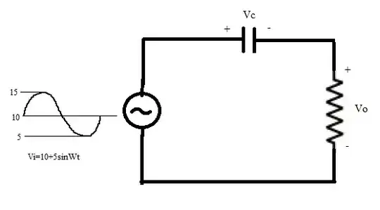
This question has been in my head for so many days. When I was studying BJT amplifiers, capacitors were used for blocking DC. It is called a coupling capacitor. When the AC signal is superimposed on DC and is applied to the circuit shown, what would be output across R(Vo)? My professor told that we will get a sine wave(5sinWt) with reference to ground and DC(10) would be eliminated. But I am not able to visualize the waveforms across C and R. I want to know how capacitor charges and discharges and blocks dc. Please help me with the waveforms.

Stephen Collings
  • 17,373
  • 17
  • 92
  • 180
bharath think
  • 81
  • 3
  • 9
  • Assuming the capacitance is "large enough", the voltage across the capacitor is effectively 10VDC. By KVL, the voltage across the resistor is the difference of the input voltage and the capacitor voltage which leaves just the AC voltage across the resistor. – Alfred Centauri Sep 13 '13 at 21:49

2 Answers2

3

One good way to look at this is as complex impedances. The resistor has an impedance of R, no matter what the signal frequency. The capacitor, on the other hand, has an impedance of \$\frac{1}{2\pi f C} \$. So you have a voltage source in series with two impedances; it's a voltage divider, and all the usual rules apply. The voltage that appears across the resistor is:

\$V_o = V_i\frac{R}{R+\frac{1}{2\pi f C}} \$

The other important thing to realize is that you can split your voltage source into two; you have one DC 10V source, and another AC source. The two do not impact each other, so you can pretend they're actually separate circuits. Just analyze each circuit separately, and add the results.

The DC analysis is simple. DC is zero frequency, so the capacitor has infinite impedance. You end up with no voltage across the resistor, and full DC voltage across the capacitor.

The AC analysis depends entirely on the capacitance and the frequency of the AC signal, which you don't specify.

Stephen Collings
  • 17,373
  • 17
  • 92
  • 180
  • How does capacitor charges and discharges in ac? Since capacitor acts as short circuit for ac, is the voltage drop across it is zero. While tracing input sine wave(consider 5sinWt), as soon as input reaches its peak value(5V) capacitor charges to peak value. At this time voltage across R is zero. When input falls below peak (say 3V) voltage across capacitor also discharges and voltage across it becomes 3V, leading to zero drop across R. Same thing continues through out a cycle. How come we get a voltage across R when all of input is dropped across C. I want AC analysis of the circuit. – bharath think Sep 13 '13 at 16:46
  • Please correct me if I am wrong in analysis. You can take f=50Hz and C=1uF – bharath think Sep 13 '13 at 16:47
  • One of your statements is that the capacitor acts as a short in AC. But you also say that the capacitor has the entire source voltage across it. These are incompatible; a short circuit, by definition, has no voltage across it. Thankfully, neither is actually true! The capacitor is neither a short nor an open circuit in AC circuits; it has a finite impedance. – Stephen Collings Sep 13 '13 at 16:53
  • The problem is that the capacitor doesn't charge instantly; it takes some time to charge, during which current is flowing through the capacitor to charge it. And while current is flowing through the capacitor, it's also flowing through the resistor. The cap is always playing catch-up to the AC input, so it never settles out at a fixed voltage and blocks the signal. – Stephen Collings Sep 13 '13 at 16:54
  • What does this sentence mean "The cap is always playing catch-up to the AC input" – bharath think Sep 13 '13 at 17:11
  • The AC input voltage is always changing. The cap voltage is always changing. The cap voltage is never equal to the AC input voltage. When the AC input reaches its peak, the cap also reaches its peak, but the cap's peak is less than the AC voltage peak. The input AC voltage is divided between the cap and the resistor; the cap gets some, the resistor gets some. The cap does not see the full AC voltage. – Stephen Collings Sep 13 '13 at 17:18
1

Firstly note that your teacher is wrong about voltage across R (V0) being 5sin(Wt), though it is correct to say that V0 will have no DC component.

To ease the problem we can consider Voltage source as a combination of a DC source and an AC source, and solve for each separately to get potential difference across each component.

Let's take DC source first:

The DC source (say a battery) will slowly charge the capacitor to a voltage of 10 volts, once it is charged the current (rather DC current) through R would be 0 A, making DC potential difference across R (V0) = 0 V

Now consider the AC source

Say the capacitor has capacitance C then it's impedance would be 1/WC

Total impedance = R + 1/WC

Clearly they are connected in series so,

V0(AC) = 5Rsin(Wt)/(R+1/WC)

VC(AC) = (5/WC)sin(Wt)/(R+1/WC)

V0 = V0(AC) + V0(DC) = 5Rsin(Wt)/(R+1/WC) [Note V0(DC is 0 V)]

VC = VC(AC) + VC(DC) = (5/WC)sin(Wt)/(R+1/WC) + 10 V

Will come up with figures if you say so. :-)

Shreshth
  • 111
  • 2