I like your solution. Since the question is about simple solutions, I have a few alternatives (some solutions provided by Microchip HERE):
1) Direct connection: If Voh (high-level output voltage) from your 3.3V logic is greater than Vih (high-level input voltage), all you need is a direct connection. (it is also required for this solution that Vol (low-level output voltage) of the 3.3V output is less than the Vil (low-level input voltage) of the 5V input).
2) If the above conditions are close, you can often boost the high-level output voltage slightly with a pull-up resistor (to 3.3V) and direct connect the signals.
3) The pull-up resistor can provide a small amount of high-level voltage increase. For more, you can use diodes and pull-up to 5V. The circuit shown will not pull-up clear to 5V, but it will increase the high-level input voltage to the 5V logic by the amount of one diode voltage drop (appx 0.7v). Care must be taken with this method that you still have a valid low-level as that is also raised by one diode drop. Schottky diodes may be used for a slight increase in high-level voltage while minimizing the undesired increase in low-level voltage. Refer to the above mentioned app note for more on this circuit.:
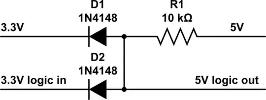
simulate this circuit – Schematic created using CircuitLab
4) If you can deal with a logic inversion (and don't require active pull-up), a mosfet and pull-up resistor may be used:
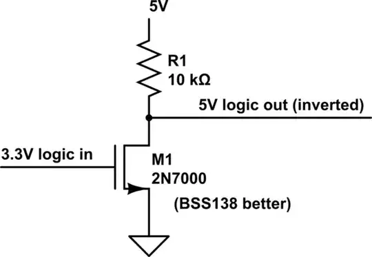
simulate this circuit
5) I know you aren't looking for a logic ic solution, but for completeness I will mention one (of probably many). The MC74VHC1GT125 is a "Noninverting Buffer /
CMOS Logic Level Shifter with LSTTL−Compatible Inputs" in a SOT23-5 or SOT-353 package. Small simple and cheap.
Apparently this subject was also discussed the other day: Step up 3.3V to 5V for digital I/O although the solution there is incorrect (thanks Dave Tweed).