9

I have a product using the MSP430 microprocessor, which has been selling for a couple years now. One of the MSP430's jobs is to communicate over async serial to a low-power radio.

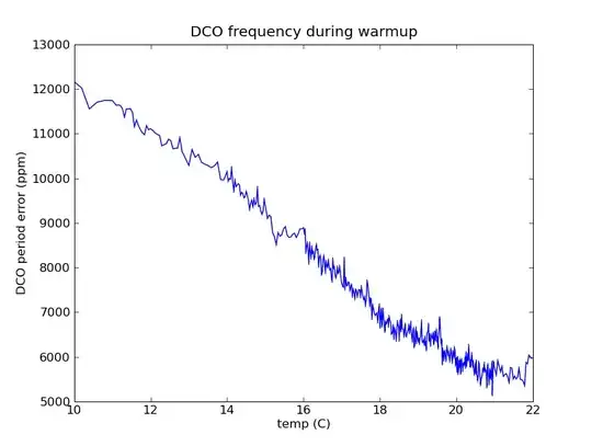
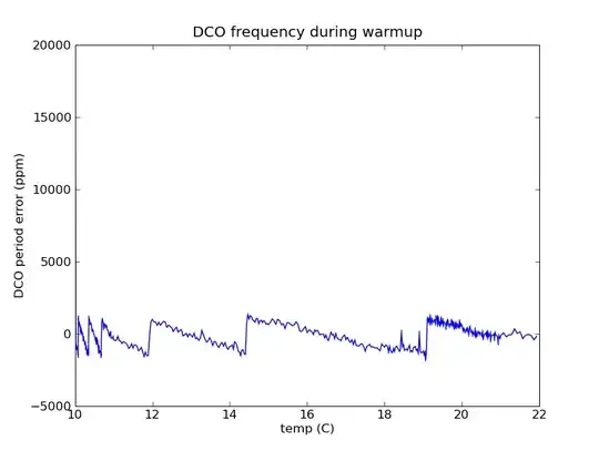
With the onset of this winter, there has been an unacceptable failure rate (several percent) in cold temperature. Investigation has found that the serial communication with the radio is failing. The baudrate generator for the serial port is fed by SMCLK, which is divided from the MSP430's digitally-controlled oscillator (DCO).

Why is serial communication failing at low temperatures?

(Note: I have already solved the problem and will be posting the answer soon. Hint: it was a software bug.)

markrages
  • 19,905
  • 7
  • 59
  • 96

3 Answers3

9

Which MSP430 are you using? The different families have different clock structures and capabilities.

The DCO will change frequency with temperature causing the USART baud rate to drift out of specification. The MSP has a temperature sensor (not very accurate). You can change the values in the DCO control registers to bring the DCO frequency back in range but this would require calibrated lookup tables covering the range of temperatures that you expect to see. Some of the MSP devices have DCO calibration tables programmed into one of the flash sectors at manufacture but these are only useful if they cover the frequency that you wish to use, and I do not think that they have temperature compensation values.

Do you have a reference crystal oscillator that you could use as a calibration source? I would always design in a 32kHz crystal and use this on the ACLK. For baud rates up to 9600 this can be used directly. For higher baud rates you will have to calibrate the DCO against the ACLK signal. The newer parts have a hardware FLL that will do this automatically.

uɐɪ
  • 3,538
  • 21
  • 27
9

So here's the answer:

The product has a 32 kHz crystal, and I had coded a routine to adjust the DCO frequency. The frequency adjustment used two timers, one from DCO and one from the 32kHz ACLK. It was driven by an interrupt off of capture/compare system, so that it could periodically recalibrate itself during operation.

Unfortunately, I inserted the initial calibration in the wrong part of my startup code, where interrupts were turned off. Therefore calibration didn't happen before the first use of the serial port, and initialization would hang waiting for a response on the serial port.

The DCO frequency starts at the factory calibrated value, which is why it was working at room temperature.

These plots tell the story:

First, the DCO-temperature curve: alt text

Now the curve after calibration is actually working: alt text

markrages
  • 19,905
  • 7
  • 59
  • 96
  • 1
    Good story! Did it cost much to fix? :D – tyblu Dec 23 '10 at 18:23
  • That's interesting that the slope changes from the first graph to the second graph. Any theories? Does tuning the DCO lower in frequency give it a worse temperature coefficient? – W5VO Dec 23 '10 at 21:19
  • Notice that the y-axis changes between the two graphs. And don't read too much into them generally. The part was frozen in a domestic freezer and the temperature was measured during warmup to room temperature with a thermocouple on a cheap MAS-345 (http://www.elexp.com/tst_s345.htm) which only reads integer degrees. Then I linearly interpolated between whole-degree changes to make the plot. – markrages Dec 23 '10 at 21:24
5

The low temperatures caused the DCO frequency to rise enough to cause the UART baud rate to rise too high? You measured the temperature and then compensated the oscillator in software?

W5VO
  • 18,303
  • 7
  • 63
  • 94