9

I am working on a project where I would like to power an RGB Led in a ambient light situation. I have prototyped this using an Arduino Leonardo and the led. Currently the project is plugged into the USB port of my computer, however I would like to use an Attiny 45 or 84 and AA batteries. I was originally thinking of using 3 AA non rechargeable batteries which would provide about 4.8 volts when fully charged. The issue is that the voltage will drop over time and I would like the led to be a constant brightness. A voltage regulator came to mind, but it would need to be efficient since I would like the batteries to last quite a while. I looked at some but was not sure the best one for my situation.

The led I am using is from SparkFun - SparkFun RGB led.

Another route would be to use two AA batteries and a step up board like is here SparkFun 3.3v breakout but again battery life is in question. I am not sure how to calculate battery usage through a step up board.

Long battery life in this situation means it would last for weeks, maybe months, of on and off use. I may be asking for the impossible with only 2 or 3 batteries though.

So my questions are would one of these options be better than the other? Would the brightness not change that much with 3 AA batteries and no voltage regulator? Would the batteries last a long time with the second option? Is there another option I have missed?

I am new to the hardware side of things, so any help is much appreciated!
sonfollower
  • 267
  • 1
  • 3
  • 9
  • 1
    It's a shame no answers yet address the question of calculating power needs of Attiny45 and step-up regulator etc. If only to explain why it isn't relevant, or not possible, to do so. – RedGrittyBrick Sep 10 '13 at 08:39
  • I am really sorry your answer was spammed, we have a site troll and he seems to have taken interest in your question. – Kortuk Sep 10 '13 at 13:30
  • 1
    Yes I would appreciate if someone could explain the power usage, even if it's only to prove you can't calculate that. Thank you to whoever removed those other troll replies. – sonfollower Sep 10 '13 at 13:55
  • The ATtiny45 can run on as little as 2.7V, so you should be able to run it directly off the batteries. – Ignacio Vazquez-Abrams Sep 10 '13 at 13:58

2 Answers2

5

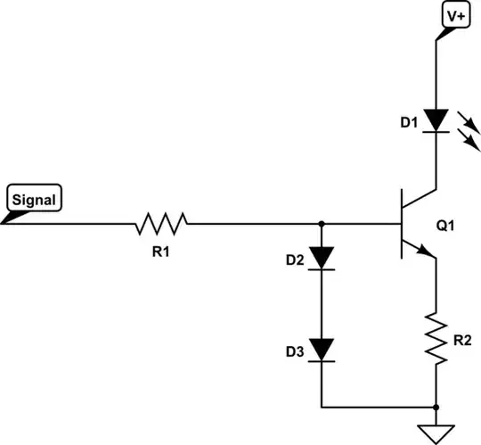
Constant LED brightness means constant current, and constant current means a current limiter.

schematic

simulate this circuit – Schematic created using CircuitLab

Select R2 as (VD2 + VD3 - VbeQ1)/ID1. Don't be afraid to use a current slightly lower than the spec (i.e. 3 to 6mA).

Ignacio Vazquez-Abrams
  • 48,282
  • 4
  • 73
  • 102
  • 1
    And of course you went and picked a CC LED. FFFFFFFFFFFFFFFF..... – Ignacio Vazquez-Abrams Sep 10 '13 at 05:24
  • 2
    To clarify Ignacio's comment: The Sparkfun RGB LED has three LEDs with a common cathode (CC). Ignacio's circuit is not suitable for use with that LED. I believe Ignacio's circuit is a variant of [this](http://en.wikipedia.org/wiki/Current_source#Zener_diode_current_source) – RedGrittyBrick Sep 10 '13 at 08:37
  • Sparkfun does sell CA LEDs, but that involves an additional acquisition. – Ignacio Vazquez-Abrams Sep 10 '13 at 13:59
  • I thought common anode and common cathode LEDs worked the same, just whether you pulled the pin HIGH or LOW? – sonfollower Sep 10 '13 at 17:11
  • @Elmer: Yes, except that using a CA LED will allow you to create 3 copies of the circuit in parallel, and control them individually. With CC you need to use a high-side limiter, and the control circuitry for that is a little more complex. – Ignacio Vazquez-Abrams Sep 10 '13 at 17:23
  • Can you show the diagram of how this would work in parallel? How do I calculate D2 and D3? Also how do I calculate R1? What is Q1? – sonfollower Sep 10 '13 at 19:36
  • D2 and D3 are small-signal silicon diodes; any scrap you can find is fine. Q1 is a NPN BJT; since you're only putting <10mA through you can again use anything. R1 is usually 1k-1.2kohms; I'm not certain of the math for this one since the diodes throw it off. For parallel circuits, pretend each of the LEDs in the CA package is isolated and build this circuit on each cathode, the connect the anode to V+. – Ignacio Vazquez-Abrams Sep 10 '13 at 20:34
  • So for the NPN BJT something like this?https://www.sparkfun.com/products/521. And for the Diode would something like https://www.sparkfun.com/products/8588 work? Why do I need two diodes, instead of just one? The led says 20mA for each color so isn't that over 10mA? – sonfollower Sep 10 '13 at 21:45
  • Those parts are adequate. You need 2 diodes since one isn't high enough to exceed Vbe *and* provide a voltage drop across the sense resistor. 20mA is the max safe sustained current for the LED, but running it at that 1) reduces LED life, and 2) reduces battery life. Most common LEDs are visible at 10mA or lower. – Ignacio Vazquez-Abrams Sep 10 '13 at 22:57
4

Find the datasheet for your cells like this example. Then take a look at the discharge curve and check how battery voltage changes during the discharge cycle. Then check how your LED responds to that using a bench power supply.

Couple things you can do from that moment:

  • Determine at which point brightness has dropped too much and if it is worth to consider the cell empty anyway;
  • Determine maximum and minimum supply voltage and use that requirements to make a better regulated power supply;
  • Increase number of batteries in series, and increase series resistor. The higher the series resistor, the lower response to varying supply voltage, but losses increase.
  • Use a current sink like proposed in one of the other answers.
jippie
  • 33,033
  • 16
  • 93
  • 160