44

I normally use an Arduino for my projects because it has 5V inputs and outputs and has 5V Vin so that makes life very easy when interfacing with 5V components. For this project I want to use a Raspberry Pi because I want to hook it up to a display. The Pi is powered by 5V so that's easy enough. It has 3.3V I/O pins however and the devices I want to interface with are 5V.

I have a device with a 5V input pin, which needs to be driven to 5V. The device has a 5V output pin, which the device drives to 5V when it outputs.

I've converted bidirectionally between 5V and 3.3V devices before, but that was with a logic level shifter that was active LOW. The circuit is the typical one with a transistor and a diode and two pull up resistors. This application requires active HIGH. This project thankfully does not require bidirectional I/O.

For the 5V to 3.3V direction, a crude voltage divider will work.

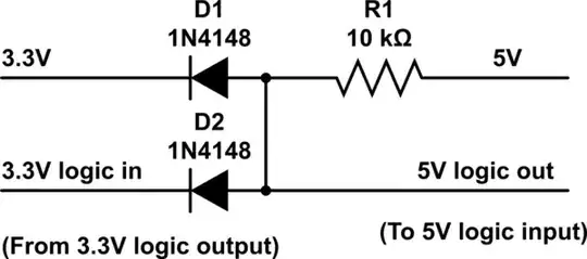
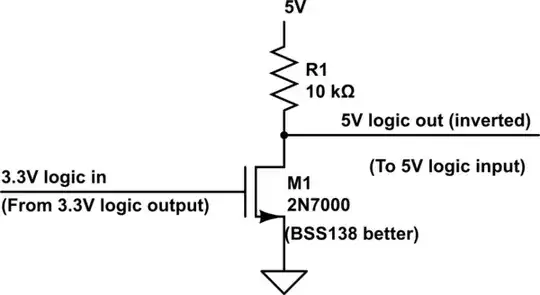
For the 3.3V to 5V direction however, I don't know of an easy solution. I did some searching and there seem to be boost-converters (DC-DC boost converters) but to build them from discrete components I need to build a PWM circuit to drive the switching.

I was just wondering if there was a simplier way to achieve this, with complexity comparable to the active low logic level shifter.

Huckle
  • 889
  • 2
  • 9
  • 15
  • Check this out different methods for interfacing.http://www.savagecircuits.com/content.php?85-Mixed-Voltage-Systems-Interfacing-5V-and-3-3V-Devices – AKR Sep 08 '13 at 07:09
  • See also: http://electronics.stackexchange.com/questions/82104/single-transistor-level-up-shifter/82112#82112 – Tut Sep 12 '13 at 12:56
  • How much current does the 5V output need to supply? Is it feeding a logic-level input? – Dwayne Reid Jul 23 '16 at 18:11

1 Answers1

37

Since Dave Tweed has pointed out the flaw in the other answer, I have basically copied my answer to Single transistor level up shifter ... Note also the interesting solution by Nicolas D in the question.

I have a few solutions (some solutions provided by Microchip HERE):

  1. Direct connection: If Voh (high-level output voltage) from your 3.3V logic is greater than Vih (high-level input voltage), all you need is a direct connection. (it is also required for this solution that Vol (low-level output voltage) of the 3.3V output is less than the Vil (low-level input voltage) of the 5V input). This solution is most often rejected due to insufficient margins.
  2. If the above conditions are close, you can often boost the high-level output voltage slightly with a pull-up resistor (to 3.3V) and direct connect the signals.
  3. The pull-up resistor can provide a small amount of high-level voltage increase. For more, you can use diodes and pull-up to 5V. The circuit shown will not pull-up clear to 5V, but it will increase the high-level input voltage to the 5V logic by the amount of one diode voltage drop (appx 0.7v). Care must be taken with this method that you still have a valid low-level as that is also raised by one diode drop. Schottky diodes may be used for a slight increase in high-level voltage while minimizing the undesired increase in low-level voltage. Refer to the above mentioned app note for more on this circuit.:

schematic

simulate this circuit – Schematic created using CircuitLab

  1. If you can deal with a logic inversion (and don't require active pull-up), a mosfet and pull-up resistor may be used:

schematic

simulate this circuit

  1. There are also many logic IC solutions such as the 74AHCT (Advanced High-Speed CMOS, TTL-compatible) series logic family. Good choices might be the 74AHCT125 which is a noninverting buffer, or the 74AHCT14, which is a hex Schmitt trigger inverter. Both of these are inexpensive and readily available. These ICs may benefit from a decoupling capacitor, especially for rapidly-changing signals.
user48147
  • 155
  • 6
Tut
  • 4,195
  • 1
  • 21
  • 38
  • I think some of your diagrams are labeled backwards. I have a 3.3V logic output and a 5v logic input. I understand how #4 works and can confirm that the label is just backwards (but it is the correct circuit for what I need). I don't fully understand #3 enough to know if it's labeled backwards or is actually backwards. That being said if I use two instances of #4 to keep the logic non-inverted I should be good to go. – Huckle Sep 15 '13 at 19:26
  • 1
    The labels aren't backwards. "3.3V logic in" indicates it is an input into the circuit I have provided ... of course it is from an output from your circuit. "5V logic out" then merely indicates that it is an output from my circuit to your 5V logic input. I will edit to clarify. – Tut Sep 16 '13 at 10:14
  • It makes sense now that you explain it, but it's backwards from the conventional point of view (where conventional point of view is meant to mean point of view of someone interfacing digital ICs). Thanks again. – Huckle Sep 17 '13 at 05:56
  • 5
    @Huckle: Tut has provided a circuit or module to be used to interface two other circuits. The standard _is_ to label the terminals or interface points from the point of view of the circuit show - not the ones you can't see. You connect your outputs to this circuit's inputs. Sometimes we need to indicate where to connect on another circuit but use arrows in those cases so it's clear. – Transistor Jul 23 '16 at 18:21
  • @Tut do you mind explaining a little more on how #3 works? I am having hard time understanding this. I am not sure what 3.3V-D1 is for :( Thank you – wbkang May 23 '17 at 00:26
  • @wbkang ... This is not really my circuit, but comes from ["Microchip 3V Tips N Tricks"](http://www.newark.com/pdfs/techarticles/microchip/3_3vto5vAnalogTipsnTricksBrchr.pdf) mentioned above. You should read the explaination beginning on P16. I think it must be an typo error where they say "the output low voltage is increased by the forward voltage of the diode D1" (I think they mean D2). It looks to me that D1 is there as a clamp to protect the 3.3V device from current flowing through D2 if the voltage at the 5V input is allowed to get too high via the pull-up resistor ... – Tut May 23 '17 at 10:40
  • @wbkang ... (continued) ... This is not always needed, but is good insurance; for example if the 3.3V logic source is a microcontroller and does not have 5V tolerant inputs, the 3.3V logic signal will likely power-up as an input until it can be configured as an output. Diode D1 as a voltage clamp would protect this pin. – Tut May 23 '17 at 10:41
  • @Tut got it, thanks a lot. I was testing it out myself and I could not figure out what D1 was for haha http://tinyurl.com/n975z7q For my little project, I ended up using 2N7000. It was very straightforward to use. – wbkang May 24 '17 at 03:36
  • 1
    @wbkang ... Good choice. Option 3 is not the "holy grail" of level conversion. It needs to be carefully applied with proper choice of both resistor and diodes (good of you to simulate). The mosfet solution is better if you can live with the logic inversion and the slight added cost. – Tut May 24 '17 at 10:39
  • Thanks, I tried #3 with my esp8266 and a 5V LED strip, and it works really well. :D – Ambrus Tóth May 04 '22 at 16:10