25

Why do we need a resistor in a Zener diode circuit, like in the diagram below?

Zener circuit

I understand it is to limit the current but how so, and why do we need it for a Zener diode?

Does selecting different values of resistors affect the circuit performance? So when we are selecting a Zener diode we look in the specifications at different reverse currents that can flow through them. But if those can be changed through resistors, can we select any Zener diaode at a voltage, without looking at the maximum current?

Circuit fantasist
  • 13,593
  • 1
  • 17
  • 48
Sherby
  • 2,316
  • 6
  • 27
  • 44
  • 2
    Kirchoff's voltage law. – Ignacio Vazquez-Abrams Sep 06 '13 at 18:58
  • The answers below are good, I think I will just supplement with this Instructible I did on Zener Diode Shunt Regulators: http://www.instructables.com/id/Zener-Diode-Shunt-Regulator/ – Kurt E. Clothier Sep 06 '13 at 22:13
  • I think what people's answers have missed is that the Zener diodes need a minimum current to work properly (usually quite a lot, in the range of 2-10mA at least) and this DOES dictate the resistor used, other than the power rating of both components, and also makes the zeners less useful as a regulator and more useful as a (normally low precision/accuracy) shunt reference voltage. – KyranF Nov 03 '14 at 08:51

6 Answers6

34

Rather than going to 'no resistor' consider what happens if we just use resistors of different (lower) values and look at the pattern. As we reduce the resistor value the current through the zener will rise. Even if the voltage source is not perfect the power dissipated by the zener will cause it to fail due to overheating.

enter image description here

Shub
  • 103
  • 4
JIm Dearden
  • 18,926
  • 30
  • 40
  • 1
    Thank You for your answers, Does selecting different values of resistors effect the circuit performance? So when select a zenner we look at different reverse currents in the specs that can flow through them. but if those can be changed through resistors, can we select any zener at a voltage, without looking at the maximum current? – Sherby Sep 06 '13 at 23:03
  • @Sherby, see my updated answer to address your comment. – Alfred Centauri Sep 07 '13 at 00:21
21

The current through the resistor is, by KVL and Ohm's law:

\$\dfrac{V_{IN} - V_Z}{R_S}\$

This is the maximum current through the zener diode and so, \$R_S\$ is chosen to limit the current through the diode to some value such that the maximum power dissipated by the diode is below the maximum power rating.

For example, if the Zener is 12V, 1W device, we would want the maximum zener current to be less than \$\dfrac{1}{12}A \$.


From a comment to another answer:

can we select any zener at a voltage, without looking at the maximum current?

The point of Jim's answer, and mine, is to emphasize the power dissipation associated with the zener diode.

Since our answers are evidently not sufficient in this regard, consider the following excerpt from a zener diode data sheet:

enter image description here

Note the first entry is the absolute maximum power dissipation. In this case, \$P_D = 500mW\$.

So, if you pick a zener diode from this family with a zener voltage of \$V_Z \$, you must pick a resistor to limit the maximum current to be (perhaps considerably) less than:

\$I_{Z_{max}} < \dfrac{P_D}{V_Z}\$

For example, if you pick the 1N5231B with a nominal \$V_Z = 5.1V\$, you must choose a resistor such that

\$I_{Z_{max}} < \dfrac{0.5W}{5.1V} = 98 mA \$

Alfred Centauri
  • 26,502
  • 1
  • 25
  • 63
6

Neither a power supply nor a Zener diode is ideal. A power supply has a very low output impedance and a Zener diode has a non-zero impedance. Without a series resistor this means:

  1. The Zener diode current will be very high
  2. The voltage across the Zener diode will be higher than specified due to its internal resistance
  3. Due to the large current that may flow the power dissipation, (\$P_{dissipated}=V_{zener}×I_{zener}\$), will be huge. Your average Zener diode will have a 400 mW or 500 mW power rating.
Peter Mortensen
  • 1,676
  • 3
  • 17
  • 23
jippie
  • 33,033
  • 16
  • 93
  • 160
  • Thank You for your answers, Does selecting different values of resistors effect the circuit performance? – Sherby Sep 06 '13 at 23:01
  • 2
    Yes it does effect performance. You have to balance the varying load current with the series resistor. The zener sinks the current that the load doesn't sink. So you really want to know minimum and maximum output currents and figure out what zener and series resistor should go with that. With regular low power zeners, you want about 1-5mA minimum zener current for good regulation. The maximum zener current can be calculated from spec'd power and zener voltage. – jippie Sep 07 '13 at 07:14
4

What is the purpose for using a zener? Short answer: To provide a voltage Vz that is not very sensible to load changes (low dynamical output resistance) - and which can be derived from another voltage source Vo which either is larger and/or does vary too much over time.

Remembering KVL, we need a part which can produce the difference Vo-Vz. A resistor in series with the Zener diode serves this purpose

LvW
  • 24,857
  • 2
  • 23
  • 52
0

Why do we need a resistor in a Zener diode circuit...?

We can answer this question by looking at the problem from a few points of view:

"Dynamic resistor"

From this functional point of view, a zener diode can be considered as a non-linear resistor that has the property of keeping the voltage between its terminals constant as the current through it varies. It does this by changing its "resistance" depending on the current. This can be illustrated by a simple experiment:

Imagine that a current I flows through a variable resistor with resistance R so a voltage drop V = I.R appears across the resistor. Our task is to keep this drop constant.

We can do it by a simple trick - when the current, for example, increases, we decrease the resistance to the same extent and vv. As a result, the product of the two quantities (the voltage drop) will not change.

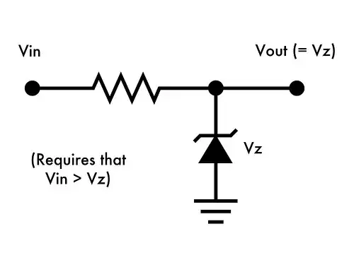
The role of the constant resistor in this arrangement is to convert the input voltage into current flowing through the "dynamic resistor" (Zener diode).

"Dynamic voltage divider"

From another functional point of view, the network of the two resistors - constant and varying, can be considered as a "dynamic voltage divider" that has the property of keeping its output voltage constant as the input voltage varies. It does this by changing its ratio depending on the input. This can be illustrated by another simple experiment:

Imagine that an input voltage Vin is applied to the voltage divider so an output voltage Vout = Vin.R2/(R1 + R2) appears across the resistor. As above, our task is to keep this voltage constant.

We can do it by another simple trick - when the input voltage, for example, increases, we decrease the divider's ratio to the same extent. As a result, the product (output voltage) of the input voltage and divider's ratio will not change.

The role of the constant resistor in this arrangement is to make a voltage divider with the "dynamic resistor" (Zener diode) in series.

"Dynamic current divider"

When a (varying) load is connected to the Zener diode, the network of two resistors - dynamic and load, can be considered as a "dynamic current divider" that has the property of keeping its voltage constant as the input current varies. It does this by changing its ratio depending on the load resistance. This can be illustrated by another simple experiment:

When the load resistance, for example, increases, we decrease the dynamic resistance and vv. As a result, the output voltage does not change.

The role of the constant resistor in this arrangement is to convert the input voltage into current supplying the "dynamic current divider".

Circuit fantasist
  • 13,593
  • 1
  • 17
  • 48
0

One item that has not been addressed here, is that you must also consider the load that will be applied to the zener, particularly if used as a shunt regulator power supply, as opposed to a fixed reference with very minimal loading. For instance, a 10 volt 1 watt zener may be specified for 500 mW which would be 50 mA. If the raw supply is 20V, a 200 ohm 1 watt (or higher) resistor would be used.

If this is to supply a 10V 67 mA load (150 ohms), there would be no current available for the zener, so it would no longer function as a regulator. So in this case you might use a 100 ohm 2 watt (or larger) resistor from the 20V source. This will supply a 33 mA acceptable zener current as well as the 67 mA for the load. And if the load is disconnected, the zener will see 100 mA which is its absolute maximum value.

You must also design the circuit to safely and effectively accommodate variations in the raw supply voltage.

schematic

simulate this circuit – Schematic created using CircuitLab

enter image description here

PStechPaul
  • 7,195
  • 1
  • 7
  • 23