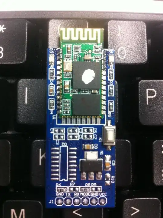
I think pg. 88 and the info/diagrams on pages 46 onward answer your question quite well:
8.5.9 Voltage Regulators
The embedded 1.8V regulator provides the core supply. The embedded 3.3V voltage regulator
is used to supply the USB pads. Both regulators are turned on at startup.
If the application is supplied with a voltage range around 3.3V or the application does not use
the USB interface, the 3.3V voltage regulator has to be turned off by writing 11 binary to
VREGCTRL.VREG33CTL.
The 1.8V voltage regulator has its own voltage reference that is calibrated through the
VREGCR.CALIB field. This field is loaded after a Power On Reset with default values stored in
factory-programmed flash fuses.
Although it is not recommended, it is still possible to override the default factory settings by writing to those registers. To prevent unexpected writes due to software bugs, write access to this
register is protected by a locking mechanism, for details please refer to the UNLOCK register
description.

So essentially it's not meant for use supplying external components, rather so you can add decoupling if it is being used. To add a pin for decoupling like this is very common (since large value caps are not feasible on the die)

