10

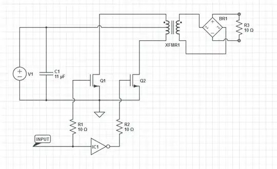
I have read What is killing my MOSFETs which seems to present a similar circuit to mine (my secondary is center tapped as well and has 2 high-speed diodes rectifying into a 10R / 400uF load)

The transformer is 12:1, my power supply voltage is between 10v and 25v at ~300mA.

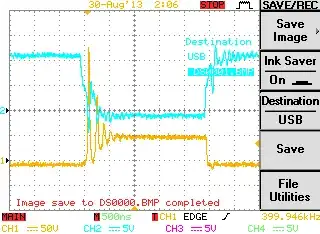
The transistors are heating due to what I believe is avalanche breakdown. I have used 50V devices and the scope shot shows ~200V devices. In each case, DS voltage rings up to breakdown (if there is sufficient energy in the circuit). I would like to push 10 and ideally 100W through this circuit. I realize the breadboard is not feasible for a 100W design, but it should do 10.

The ringing is at 2.x MHz. The power supply input capacitors are not low-esr or particularly high valued.

Schematic Photo Scope shot

HL-SDK
  • 2,539
  • 1
  • 19
  • 26
  • How comes the DS voltage of the transistor settles to 50V (or the orange trace is not the transistor's voltage)? – Vasiliy Aug 30 '13 at 18:09
  • I do not know. I am measuring one of the drains with respect to ground. I have verified my power supply is putting out 24.2 volts. I measuring the power supply at VIN/GND results in ~24 volts. Interesting... I have confirmed the winding diagram is correct for the transformer. – HL-SDK Aug 30 '13 at 18:13
  • The source of 2x voltage on your FETs is described in the same question you've already linked (answer by Andy Aka). I still can't see how this could be the steady state voltage, but one thing is sure: these FETs are not good for your application. These poor FETs are doomed to reach their DS breakdown voltages in this configuration. – Vasiliy Aug 30 '13 at 18:29
  • Well I can throw in 1200V SiC parts we have lying around but that is treating a symptom, not a cause. – HL-SDK Aug 30 '13 at 18:31
  • BTW, it looks like you FETs are not attached to the heatsink (which is lying under the breadboard). Have you done this just to take a picture, or this is the way your circuit operates? – Vasiliy Aug 30 '13 at 18:35
  • @VasiliyZukanov, The transistors are 20mOhm devices: conducting 10 amperes, they will only need to dissipate 2 watts. No heatsink should be required for this application – HL-SDK Aug 30 '13 at 18:56
  • 1
    I think that usually the specified resistance is \$R_{ON}\$ - the resistance when the transistor is in steady conduction. It is hard to predict what will be the resistance during transients (which are relative long in your case). Also, the power dissipated in Gate electrode due to switching is not included in this calculation. I don't think it is the root cause, but I think your devices will be better off with heatsinks (at least small ones). – Vasiliy Aug 30 '13 at 19:03

2 Answers2

5

It is because of the center tap. Look at the left part of the transformer only.

You have two inductors in series. When you pull one inductor to ground a current starts to flow and the other (magnetically coupled) inductor will try to induce the same current, pushing the other transistor's drain voltage up until it breaks down.

jippie
  • 33,033
  • 16
  • 93
  • 160
  • 1
    Thanks, now to solve some of my problems: how can I re-route/snub this energy? It is severely limiting my power limit for this design. A fast diode from the drain to center tap? sounds wasteful – HL-SDK Aug 30 '13 at 18:27
  • Use a full bridge? – jippie Aug 30 '13 at 18:28
  • That diode would need to be biased the wrong way anyway, it shorts the transistor. – jippie Aug 30 '13 at 18:41
  • @jippie, is that true about the diode being biased the wrong way? The anode would be on the FET drain and the cathode would be on the center tap. Current is traveling from the center tap, through the half winding and down through the 'ON' FET. When that FET turns off, the current needs somewhere to go, so the diode would provide a path without generating the huge voltage spike. – Peter Aug 30 '13 at 19:14
  • 2
    This type of design will produce 2x supply voltage on the drains of each FET - trying to short anything above 25V to centre-tap means a fire. – Andy aka Aug 30 '13 at 19:31
  • @Peter The current through the diode will counter the magnetic field from the 'active' winding, reducing the output power of the transformer. – jippie Aug 30 '13 at 19:58
  • @Peter Andy makes a good point in his answer: a zener would work better, but would dissipate more power (P = U × I). – jippie Aug 30 '13 at 20:09
3

If your power supply voltage is 25V and the transformer (and switching) was absolutely perfect, you would see 50V on the drains of the MOSFETs and that is a fact. Your MOSFETs should be rated at at least 100V.

Imagine the centre tap of the primary is like the fulcrum of a see-saw; you pull one side down to ground and magically (or not) the other side rises to twice the power supply voltage. The two halves of the primary are strongly coupled and this is what you get with coupled inductors (aka a transformer) irrespective of the secondary and what load is on it.

The ringing is because the transformer aint perfect - not every bit of magnetic energy supplied supplied via the centre tap will be induced into the open circuit winding - you have leakage inductance and a toroid (for instance) is good if you can get better than 98% coupling.

The 2% that isn't coupled still takes energy from the supply and it has nowhere to go when that side of the transformer goes open circuit. What it finds is the open circuit drain capacitance of the MOSFET and it "rings" and this ringing can be deadly serious too.

Rate your transistors at a higher voltage, apply a 33V zener and diode snubber back to the centre tap from each drain (at least this way you can steal a bit of energy back).

Andy aka
  • 434,556
  • 28
  • 351
  • 777
  • I'm not convinced the voltage is limited to two times power supply voltage. I think the current in one half of the winding will try to 'copy' the other half winding's current (disregarding the load for sake of argument). For the current to rise that high it will increase its voltage indefinitely (theoretically). Of course the load will 'tame' this behavior a fair bit, but not necessarily to only twice the power supply voltage. – jippie Aug 30 '13 at 20:05
  • 1
    @Jippie. No, it won't copy the current. The current you refer to is the magnetizing current that any transformer has. On zero-load there is still a magnetizing current and this is always needed on a transformer and doesn't contribute to transformer action other than as a leakage inductance in the short space of time whan one half of the primary open circuits before the other half is pulled to zero volts (ish) i.e. a few tens of nano seconds. This causes the ringing. Once the other side has pulled to gnd you've got regular transformer action and the "open side" mirrors the pulled side. – Andy aka Aug 30 '13 at 21:07
  • @Jippie. Alternatively, the average voltage across one half of the primary has to equal zero and that is a fact. Ditto both halves and ditto the pair of them. – Andy aka Aug 30 '13 at 21:09