16

I have to provide some isolated inputs that accept 12-24V. There should be some protection against reverse polarization, transient over-voltage and permanent over voltage (up to 40V) to some degree.

So far, I came up with the following circuit: enter image description here

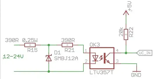
  • R15+R21 limit the forward current to ~14mA@12V and 30mA@24V
  • D1 TVS diode (breakdown ~@13V) protects against transients and voltages above ~26V
  • D1 protects against reverse polarization
  • R15 limits the current in case of reverse polarization or when D1 is clamping

This design seems suspiciously simple. Do I miss something or should it work as desired?

EDIT:
R21 was meant to provide some additional transient over-voltage protection (ESD), because the TVS diode won't clamp instantly. This was also the reason for choosing a TVS diode instead of a normal one. Is this overkill?

As pointed out, If was somewhat high. I will consider something more like 580 Ohm for R15 and R21 to limit the current to 10-20mA.

LTV357T

AKR
  • 2,273
  • 4
  • 22
  • 34
Rev
  • 10,017
  • 7
  • 40
  • 77
  • Datasheet says ratings are less compare to what you are feeding http://www.mouser.com/catalog/specsheets/LTV-357T%20Series-1308.pdf – AKR Aug 29 '13 at 15:42
  • @AKR: It just states "CTR : MIN. 50% at IF = 5mA", but maybe I miss something? As far as i can tell according to the diagrams and other tables, its perfectly fine to have IF around 10-30mA. – Rev Aug 29 '13 at 17:03
  • I am trying to point out about the Vf which is max of 1.4V and you are feedind 12 to 24 V. – AKR Aug 29 '13 at 17:09
  • @AKR: Thats why there are resistors in series, limiting the current and dropping the rest of the voltage. – Rev Aug 29 '13 at 17:17
  • 1
    I know it's several years down the line on this thread but if the OP (original poster) or any other contributors are reading, just a word of thanks for the circuit and subsequent discussion. It's been a great help in a ras-pi based gate controller program I have been working on. The biggest problem I have is very noisy limit switch inputs and I'm hoping the above will resolve that – Neil Parker Dec 21 '21 at 09:20

2 Answers2

11

The circuit is good for protecting the diode. I don't know of a better one.

You don't have to worry about protecting the diode from transients. If a large current ( < 1A) flows through the diode for a microsecond, it won't hurt the diode. You can get away with a regular zener diode instead of a TVS.

You might consider using a lower zener (TVS) voltage, say 5V. That will cause less variation of diode current between 12V and 24V input voltage.

Optoisolators tend to age poorly, and the CTR will decline over time (or at least they used to, maybe that's been improved). So it's a good idea to drive the diode with more than the minimum current to be sure that over time the input drive will continue to drive the output. 10mA is probably a good number for an opto LED spec'd at 5mA minimum.

blakedude
  • 166
  • 3
4

Your resistors are a lot smaller then they need to be.

With two 390Ω resistors, you're getting ~15 mA @ 12VIn. The opto you have is characterized at both 5 mA vF and 20 mA vF. Unless you need fast response, running the LED in the opto at 5 mA shouldn't hurt anything.

It's probably worth making sure you're feeding the opto into a schmitt-trigger input, if it's going into any logic that can't handle slow transitions.

Also, there is no reason to bother with the two resistors. Just put the diode directly across the optocoupler. This will reduce the dissipation in the case of someone connecting the power backwards.

Connor Wolf
  • 31,938
  • 6
  • 77
  • 137
  • Thanks for the response. Are you sure you got the right data sheet (LITEON LTV-357T)? Mine rates If=20mA as nominal and 50mA as absolute max. The idea with the second resistor was to prevent a short and limit the current through the diode. – Rev Aug 29 '13 at 09:03
  • The idea was you *only* have R15. It's R21 that is unnecessary. Also, the nominal doesn't mean it can't operate at a lower vF, it just means that that's the point they characterized it at. – Connor Wolf Aug 29 '13 at 09:04
  • Oh, also, the diode should probably be a normal diode, not a zener. I actually thought it was a schottky, but I'm not sure what your schottky diode primitive looks like. Zeners should not have right-angle lines like that, the proper zener symbol has the lines angled at ~45°. – Connor Wolf Aug 29 '13 at 09:05
  • R21 was meant to provide some additional transient over-voltage protection (ESD), because the TVS diode won't clamp instantly. This was also the reason for choosing a TVS diode instead of a normal one. Is this overkill? – Rev Aug 29 '13 at 09:10
  • Regarding the forward current, i thought it would be best to drive the LED in the area where the CTR is best. – Rev Aug 29 '13 at 09:12
  • 5 mA LED current will generate a worst-case of 2.5 mA (50% minimum CTR for this part) at the output side, which is rather iffy in practice. Not a good recommendation. – Anindo Ghosh Aug 29 '13 at 09:18
  • @AnindoGhosh - The pull-up on the transistor collector is 20K. Even if the C-E current was only 1 mA, it would still be able to pull the output down 20V. As I said, your edge-rates are going to be quite slow, but it should still switch fine. – Connor Wolf Aug 30 '13 at 04:20