2

This is the circuit i'm creating.

enter image description here

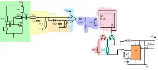
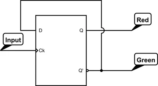
BTW: The light pink area is a D flip flop.

(From left to right)

  • The green area is a microphone with a preamp.
  • The signal passes through a low pass filter, with a cutoff frq. of 300Hz (Yellow)
  • It then passes through a peak detector, which holds on to the peak value until the capacitor discharges [discharge speed controlled by a 150Ohm var. resistor] (Orange)
  • An op amp is acting as a comparator. If the signal that comes off the low pass filter is higher than the (smooth) peak detector signal, it should output 5v, other wise, 0v. (Light blue)
  • This signal then gets smoothed by another peak detector, which discharges 0.25 seconds. (Purple)
  • A D FLip Flop, toggles between the Q and Q' terminals, which should turn on either transistor (Pink)
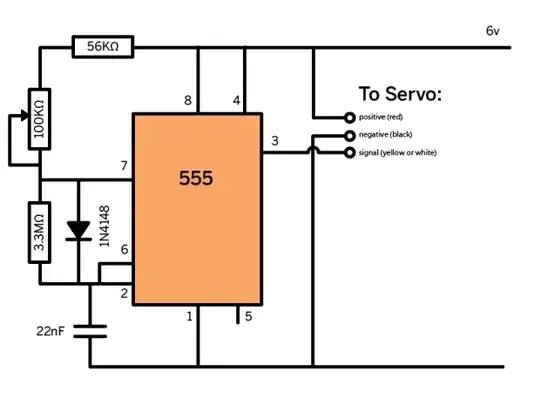
  • The change in resistance across the 555 timer circuit, replaces a 100k Ohm potentiometer, being turned backwards and forwards. I hope that this will toggle a servo between to definite positions.

In essence, all I want is for the servo to toggle between to definite possitions, to the beat of music.

  • Is there an easier way to achieve my essential goal?
  • Does my circuit work like I think it should?
  • Do you have any ideas on how i could improve/fix this circuit?

The original PWM Controller:

enter image description here

  • I debated on writing an answer for this Q. There is just so much wrong with this that it is difficult to really know where to start (and how to end). The interface between the green and blue is not biased correctly. The transistor in blue needs a pulldown on the output. The peak detector isn't going to work like you want (you want "RMS peak", not "peak peak"). The voltage comparator needs a pullup on the output (unless it is really an opamp). And I suspect that there are issues with the 555+control circuit but there isn't enough detail to say for certain. –  Aug 28 '13 at 17:30

2 Answers2

2

That's a D flip-flop with the input connected to the clock and the Q' output fed back into D.

schematic

simulate this circuit – Schematic created using CircuitLab

Ignacio Vazquez-Abrams
  • 48,282
  • 4
  • 73
  • 102
0

Your variable resistor only has two terminals (should be 3) and your input stage is questionable:

  • electret microphones need power / bias current
  • currently this is only supplied by base current from the transistor
  • what is the rolloff frequency of your filter, and have you taken the microphone impedance into account?
  • the "output" of the transistor is a current, which must all flow into the opamp, or through the varistor; but the opamp input impedance is high. You may need a 10-100k resistor to ground from the output of the transistor to pull that side of the branch down.

Have a look at Can I use a PNP Transistor with an Electret Microphone to get an non-inverting output for my Arduino? for a good discussion on how to build the kind of amplifier you're looking for.

Edit: I'm not convinced that your resistor switching arrangement will have the desired effect on the PWM module, but without its schematic we can't tell.

pjc50
  • 46,540
  • 4
  • 64
  • 126