BJTs are mostly used in common emitter, sometimes common collector configuration. I rarely see common base. When would you use a BJT in common base? For instance, what parameters are different from common emitter?
Asked
Active
Viewed 1,491 times
22
-
probably because of how wide and broad the question is, I would just ignore it. When you ask more detailed questions it wont matter. – Kortuk Aug 26 '13 at 14:24
-
http://en.wikipedia.org/wiki/Common_base – Aug 26 '13 at 14:27
-
3@DavidKessner, I just registered today, but I have looked at questions and answers here for a couple of days. Many questions may be answered elsewhere, for instance on wikipedia. – The Resistance Aug 26 '13 at 14:30
-
3@user28009 I'm looking forward to an answer by someone with a clue (as opposed to Trolls). When I first read your Q, I thought it was absurd. After doing a little bit of research, I decided that there was something I needed to learn here. Sometimes it takes a "newbie" to show us veterans that we don't know it all. +1 for that. – Aug 26 '13 at 14:34
-
2@user28009 I think the main reason a WikiPedia link was posted (I was going to do so myself) is that common base arrangement is not something most of us use *commonly* (mostly UHF stuff), so we aren't qualified to answer any better than the WikiPedia page has it. In other questions and answers, you would often see insight in answers here, that are not there in WikiPedia - admittedly not always, but that's the ideal anyway. – Anindo Ghosh Aug 26 '13 at 14:35
3 Answers
13
A common-base configuration is characterized as having near-unity current gain (with significant voltage gain) and a relatively low input impedance. Typical applications would include RF power amplifier (50Ω source) and the upper transistor in a cascode configuration, where it is used for isolation.
Dave Tweed
- 168,369
- 17
- 228
- 393
-
The transistor T1 in this [article](http://www.circuitsonline.net/forum/view/107436) in the input stage is in Common Base configuration for high voltage gain. – jippie Aug 26 '13 at 20:17
6
A Common Gate or Common base amplifier is perhaps the third or fourth most commonly used amplifier in the design of op-amps. You just don't necessarily recognize it as such. It plays an integral role in the design of cascode amplifiers. Wit the addition of the GG/GB amplifiers the bandwidth goes up and things are generally improved.
placeholder
- 29,982
- 10
- 63
- 110
-
Thanks for your answer. Can you elaborate on "things are generally improved"? – The Resistance Aug 26 '13 at 14:43
-
This is a Q & A format site, discussion about cascodes in the comments and extended comments are not generally apropos. If you're interested read up on differential amplifiers and cascodes, it will take you far. – placeholder Aug 26 '13 at 15:00
-
2@rawbrawb: nobody said you have to start a discussion in comment. You might edit your answer. (Personally I also think "things are generally improved" is a bit vague.) – radagast Sep 06 '13 at 06:43
1
The most prolific use of common base is in every single op-amp (probably) ever made. Here's a very simple idea of what I'm talking about: -
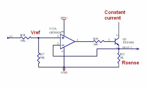
With -Vin at some arbitrary DC voltage somewhere between +Vs and -Vs, the (other) signal (on +Vin) is "seen" at the emitter of both transistors. This acts as an input to the emitter of the left-hand BJT and +Vin (with or without some amount of amplification) appears on the the collector and Vout (in phase).
I'm not going to go into the different aspects of input impedance into the emitter because this is covered by the comments.
Andy aka
- 434,556
- 28
- 351
- 777