24

I don't really understand how these diodes in this circuit and similar circuits (like driving a relay circuit) protects the controller circuit from the energy stored by the inductance of the coil. I really appreciate if someone could graphically explain it. ( I mean how the the diodes block the current and etc)

the second question about this circuit is the capacitor. what happens if it isn't there?

enter image description here

Scott Seidman
  • 29,274
  • 4
  • 44
  • 109
Mehrdad Kamelzadeh
  • 959
  • 4
  • 11
  • 22

4 Answers4

22

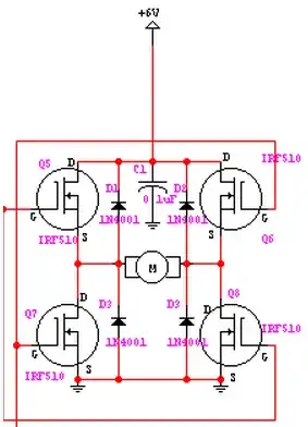
The diodes in this application are not there to block current, but to allow a low-impedance path for the coils to discharge themselves through. If such a path is not provided, then when the coil's supply is stopped at each cycle, the stored magnetic energy must find a path for discharge. This results in the coil expressing an arbitrarily high reverse voltage across its ends till the energy finds a way to get out.

Result: This high voltage shows up across the MOSFETs, which die a miserable death.

The diodes thus provide a short-circuit discharge path, dissipating this energy as heat within the diode.

The capacitor's function is to act as a local energy store, to provide some of the energy required by the motor during the initial spike of each turn-on, and storing back some of the energy that kicks back onto the power rail at each turn-off. Without the capacitor, the current spikes at each edge would completely need to be served by the supply rail. As any supply connection will have some resistance, these current spikes thus result in voltage dips on the supply rail.

In simple terms, the capacitor smooths out the spikes due to temporary power demand and temporary power surplus, as the coils are energized and de-energized.

Anindo Ghosh
  • 50,188
  • 8
  • 103
  • 200
  • When one pair of transistors switch off and the other pair don't switch on immediately, the "back-emf" current then has to flow through C1 and / or the power supply itself. Under normal PWM control this happens momentarily between one pair switching off and the other switching on. That's how I see it. – Andy aka Aug 26 '13 at 10:00
  • @Anindo thanks for your answer but I don't understand two part of that. first what does it mean "die a miserable death"? second "these current spikes thus result in voltage dips on the supply rail"? – Mehrdad Kamelzadeh Aug 26 '13 at 10:52
  • @MehrdadKamelzadeh MOSFETs have maximum voltages that they can cope with, across Drain and Source (actually across any two pins), which are typically specified in the datasheet. When the coil back EMF exceeds this value, the MOSFET gets permanently damaged. While enhancement mode MOSFETs typically incorporate a body diode, that internal diode is generally not fast enough / of low enough forward voltage, to successfully shunt this back-EMF and protect the MOSFET. Hence the external diode saves the MOSFET from being damaged, i.e. dying. – Anindo Ghosh Aug 26 '13 at 10:58
  • If there is a spike in current demand, this current will cause a momentary voltage drop on the supply rail as seen at the H-bridge - this is due to induction and resistance effects of the supply wire from the power source to the H-bridge, even assuming an infinitely stable power supply. Providing a local capacitor of sufficient value will smooth out these local voltage drops i.e. dips. – Anindo Ghosh Aug 26 '13 at 11:02
  • @AnindoGhosh you are a perfect teacher. thanks. But one more question (which I promise to be the last one ;) ). how should I have known that it must be 0.1uf? is there a way to calculate it? – Mehrdad Kamelzadeh Aug 26 '13 at 11:09
  • @MehrdadKamelzadeh In applications like this one, for moderate current loads I generally use one 0.1 uF ceramic capacitor in parallel with a 10 uF electrolytic. For a high current load, I might use a 0.1 uF and a 100 uF in parallel. Why those specific values? Because I am lazy, I just follow a general rule of thumb that has been discussed in other questions on this site before. Can ideal values be calculated? Sure, but not something I would bother about. – Anindo Ghosh Aug 26 '13 at 11:46
  • @AnindoGhosh according to what you said about the diodes in this circuit, don't you think that the low side diode (d3, d4) are reversed? Because when the motor stops the voltage at motor nodes are bigger than ground. Am I right? – Mehrdad Kamelzadeh Aug 26 '13 at 15:54
  • @MehrdadKamelzadeh No. If you put the diodes the other way around, they'll short current to ground during MOSFET conduction. – Anindo Ghosh Aug 26 '13 at 15:58
  • @AnindoGhosh yea you are right. But you know what? I am designing this circuit but instead of the high side NChannel MOSFETS, I want to use PChannel. But I got confused with their diodes. Should they be the same as this circuit or reverse? – Mehrdad Kamelzadeh Aug 26 '13 at 16:19
  • @AnindoGhosh when the motor stops, as you said we have a high voltage at it nodes. So it seems that the path it finds to discharge its energy is always via D1 and D2. When the D3 and D4 do their job? – Mehrdad Kamelzadeh Aug 26 '13 at 16:37
9

To supplement Anindo's fine answer, specifically, the voltage across the inductor (i.e., in this case the motor) is $$ L \frac{di}{dt} $$

Thus, when current is cut off suddenly (exactly what an h-bridge wants to do, especially when controlled as a PWM), \$\frac{di}{dt}\$ gets extremely large and there is an associated very large spike in voltage. The diodes protect the MOSFETs from these spikes.

Scott Seidman
  • 29,274
  • 4
  • 44
  • 109
  • when the motor stops, as you said we have a high voltage at it nodes. So it seems that the path it finds to discharge its energy is always via D1 and D2. When the D3 and D4 do their job? – Mehrdad Kamelzadeh Aug 27 '13 at 13:44
  • 3
    When the voltage spike is negative. Current can flow in either direction across a motor, so the spike can be of either sign. – Scott Seidman Aug 27 '13 at 14:46
  • Scott, since the current can flow in either direction, does this mean that this capacitor must be non-polarized? Or does it matter in this case? I ask this because the large electrolytic capacitors are polarized. – Link H. Aug 18 '20 at 12:38
  • @LinkH. So long as one side of the cap is at Vcc and the other is at ground, the cap is polarized just fine. Current can flow in any direction. – Scott Seidman Aug 18 '20 at 15:54
  • @LinkH. -- I don't mean to seem persnickety, but I'm seeing ONE diagram with a cap in this whole QA. If you have a question about a specific config, post it as a new question. – Scott Seidman Aug 19 '20 at 15:25
7

The capacitor is there to absorb noise coming from the motor, which otherwise would mess with your power supply. 100nF is a very low value, however. Depending on the motor's power I would use 10uF to 100uF, but also leave the 100nF in.

The Resistance
  • 960
  • 8
  • 17
2

some of the above is correct but the diodes and capacitor are there so that the back emf/inductive energy stored in the motor is sent back to the cap as a storage reservoir, the energy isn't dissipated in the diodes, without the cap there the circuit would probably destroy itself as the energy would have nowhere to go until the voltage reached a point where a discharge path was created.