3

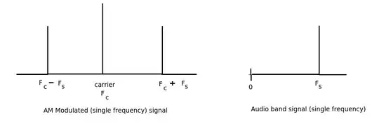
If I have an oscillator at 10 kHz outputting 5 W, using AM, like this.

enter image description here

Where does the power in the sidebands come from? Is the power the result of the harmonic relationship between the carrier and it's 2x harmonic and it's 1/2 x (?!) harmonic?

Is the power the result of a fundamental electromagnetic physical principle that power at a certain frequency x always spreads out a bit? And the higher the wattage, the more the spread?

Is this power intentionally generated to produce an RF envelope with a certain bandwidth with the MOST power at the center? If so, don't very high and very low modulating signal frequencies receive attenuation?

And 2) if so, when we say we are broadcasting a 10 kHz, we are really saying we have the most power at. 10 kHz, but we certainly are 'using' a lot more frequency space. And if so, why do we need all that space, I though the AM was transmitting information using modulation of the amplitude of the carrier to propagate a voice waveform.

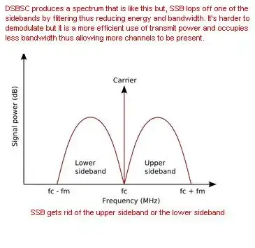
What are the peaks in the sidebands caused by?

Andyz Smith
  • 395
  • 2
  • 12

2 Answers2

1

The diagram is misleading you by representing the signal as some perfectly distributed band.

The sideband frequencies are the result (literally the product) of the audio or signal frequencies acting on the carrier. If there was only a single (sinewave) signal the spectrum would look like this.

enter image description here

JIm Dearden
  • 18,926
  • 30
  • 40
  • So, this is CW . Where only bineary state of a single sine wave are used to serially transmit information. If I tried to send my voice over one sine wave it would be garbage output. ? It woud just be on or off when ever my voice hit a particular note, and unintelligible? And if I had say **50 high power output stage transistors** , I could be switching sine wave at different frequencies throughout and actually send 50 different **serialzed** messages, uninterfered with, through this system? – Andyz Smith Aug 24 '13 at 13:20
  • @AndyzSmith No. CW would simply be the tone being switched on and off. The diagram shows only 1 particular frequency in order to **clarify** what is happening with the carrier and the sidebands produced by that particular frequency. A normal audio signal would be a spectrum of frequencies ranging from about 30Hz up to about 2.5kHz (not the full audio range). This means the sideband take up a 2x 2.5kHz i.e 5kHz with the carrier frequency centred. – JIm Dearden Aug 24 '13 at 15:11
1

Here's a better diagram that might explain your confusion. I'm using baseband audio from 20Hz to 20kHz modulating a 50kHz carrier for the example: -

enter image description here

I'm sorry it's a bit hard to read but if you magnify your web browser it'll be easier. The power in the sidebands comes from both the original baseband signal and the carrier (even though it isn't present anymore). The full spectrum of the final picture goes from 30kHz to 70kHz because it is twice the baseband spectrum of 20kHz.

And now the (simplified) maths and it comes down to accepting that: -

\$sin(a).sin(b) = \frac{1}{2}(cos(a-b) - cos(a+b))\$

\$sin(b)\$ can be regarded as the modulating signal and for simplicity \$b = 2\Pi Ft\$ and let's choose \$F\$ to be a single frequency of (say) 5kHz.

\$sin(a)\$ can be the carrier at 50kHz.

Now look what \$sin(a)sin(b)\$ yields in the formula. There is a \$cos(a-b)\$ and a \$cos(a+b)\$ term. These are new frequencies of 45kHz and 55kHz. OK they're cosine waves but that just means they're shifted by 90º to the equivalent sinewave.

Andy aka
  • 434,556
  • 28
  • 351
  • 777
  • The power in the sidebands comes from the oscillator output stage we control with the input signal? So actually the 'transmitting' on 50 kHz is really allowing the output stage to travel and radiate electromagnetic energy at 50.1 kHz at 4 W at 50.2 kHz at 4 w, a 50.3 kHz a 4 w and so on , forever. S when we say 'carrier' we just mean, well, if I produce a high amplitude baseband modulation input 'right snack in the middle of my baseband bandwidth' , then I will get a very high energy output 10 w at **exactly 50 kHz**. – Andyz Smith Aug 24 '13 at 13:13
  • If the baseband power is 1W and the carrier is 1W and we used a perfect mixer (aka analogue multiplier because that's what it is) then the composite signal will be 2W; 1W in the lower s/b and 1W in the upper s/b. Power comes from both carrier (single frequency) and the baseband and for DSBSC there will be no power at 50kHz because there are no dc components in the audio. – Andy aka Aug 24 '13 at 13:17
  • The power comes from the output stage of the transmitter, period? – Andyz Smith Aug 24 '13 at 13:21
  • @AndyzSmith actually the power comes from the power supply that feeds the PA (LOL) but I'm talking about the \$relative\$ power levels in the signal and how they are distributed in the modulated spectrum. It doesn't matter if it's 1W or 1kW, the spectral shape remains the same and ignoring the PA, the power comes equally from the original carrier and the original modulation signal at baseband. – Andy aka Aug 24 '13 at 13:49
  • So, if I have a high amplitude spectral peak n my baseband audio envelope at 5 kHz ( sounds like a dial tone, but not a whistle ) then when that baseband audio is **controlling the frequency** of a high power output transistor oscillation frequency the I will get a electromagnetic radiated energy peak at 55 kHz and 45 kHz. – Andyz Smith Aug 24 '13 at 13:49
  • I'm trying to clarify that the modulating signal typically contains, for all practical purposes, no power. – Andyz Smith Aug 24 '13 at 13:50
  • @AndyzSmith A theoretical DSBSC modulator takes equal power from both signals. But for practical realization of a DSBSC modulator, the signal representing the baseband may be 1mW and the carrier may incidentally be 3mW BUT when "combined" and with appropriate amplification you might get 100W - my explanation is trying to ignore practical realizations of imperfect modulators/PAs by looking at the power content of the finished DSBSC signal and pointing out where various parts of the spectrum theoretically come from. – Andy aka Aug 24 '13 at 14:00
  • So, the carrier is artificially generated to excite the output transitor to create a 'pilot' , artificial electromagnetic RF energy peak at 50 kHz. When this artificial signal is mixed with the baseband audio ( pre amplification ) and fed to the the output transistor frequency control loop the output transistor is actually excited in all sorts of frequencies, **and actually oscillates at different frequencies all along the bandwidth**? – Andyz Smith Aug 24 '13 at 14:17
  • @AndyzSmith the carrier is artifically generated and yes, you can think of it as a pilot that guides the baseband to where the carrier (on its own) would have been. Common modulators produce upper and lower sidebands but only one is needed theoretically to recover the original baseband signal. That's where SSB comes in (as per your previous question) - SSB filters out one sideband. – Andy aka Aug 24 '13 at 14:46
  • I'm thinking of it as a pilot for the demodulator. So there is a high energy reference signal that the demod circuit can use the make sure it is centered on the RF bandwidth, so it can effectively transpose the original baseband audio without distortion. Without this pilot you need a highly stable reference frequency source. – Andyz Smith Aug 24 '13 at 14:50
  • But I'm not thinking of it as **guiding the baseband** anywhere. The baseband is guided onto the RF bandwidth by the fact that **the baseband alters the resonant frequency of the high power output transistor circuit.** – Andyz Smith Aug 24 '13 at 14:52
  • @AndyzSmith that would be incorrect. You do not need resonant circuits to produce AM and even though you might use one to ensure you are not transmitting beyond your allocated limits, its bandwidth will cover the whole baseband x 2 frequency. – Andy aka Aug 24 '13 at 15:04
  • But you need power at and around 50 kHz. Where do you get that? – Andyz Smith Aug 24 '13 at 15:07
  • @AndyzSmith A perfect theoretical DSBSC modulator takes power from the carrier (50kHz) input and the modulation signal (5kHz or audio or whatever) input. The maths of multiplying the two signals together means you get sidebands either side of 50kHz. You only get some power at 50kHz when the modulating signal is biased so it doesn't go negative i.e. the resultant carrier may droop down to a low value but it doesn't invert. – Andy aka Aug 24 '13 at 16:28