I am trying to understand the detailed operation of a VSWR meter, and found an excellent account in the article "An Inside Picture of Directional Wattmeters" by Warren B. Bruene W0TTK in QST for April 1959.
However there is an unexplained difference between the two circuits (attached) from that article. In Figure 7 the two voltages ev and ei add (for the measurement of the forward component) and are then rectified by the diode and available for measurement by a d.c. meter. Figure 8 shows another design -- which is used in a commercial directional coupler, the Collins 302C -- where the current sampler is a current transformer, but here the diode comes between a resistor that has ei across it, and the capacitive voltage divider for ev. Can anyone please explain why this change is made?
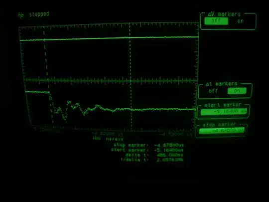
Neither an extensive internet search, nor poking about with an oscilloscope in a Collins 302C, which a friend has kindly lent to me, brought any enlightenment.
(Sorry, I can't find a way to do the subscript characters for ev and iv)