4

first post here

I was wanting some help with a fuzz pedal kit I recently bought on ebay. I'm relatively new to electronics and I'm no genius in this area, but I've been really frustrated for the past few days. I built this circuitboard exactly as I was instructed, yet it doesn't work and I can't figure out why.

The guy never send me a circuit diagram, but instead, more of a literal interpretation of what it would look like. Here it is -

enter image description here

If that is a little hard to make out, here is my own circuit diagram that I drew up (I apologize in advance for the poor quality and clarity of the diagram, I've never drawn one before)

enter image description here

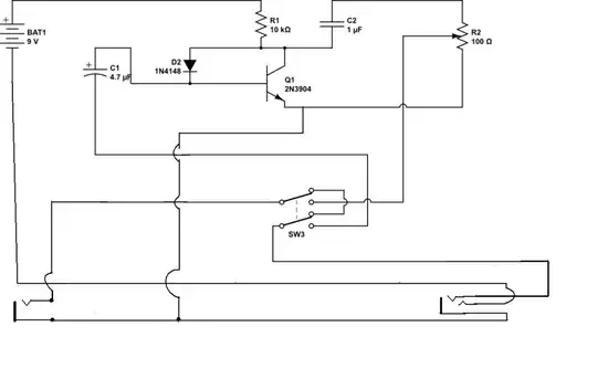
When the switch is off, and the effect is bypassed, the guitar sounds fine, as if it was plugged in to the amp with no alteration to the sound. When I turn the switch on, I get a really crappy result. If the potentiometer is turned all the way to the left, I get a little bit of the original signal, but it's quiet and a bit lo-fi. When I turn the potentiometer to the right, I lose sound altogether... silence.

Another thing worth mentioning is that it doesn't seem to make a difference whether the battery is plugged in or not. I've tested the battery with a voltmeter and it's definetely working and has a lot of juice. I've also tested the battery socket on a breadboard incase the socket was faulty, but the socket is working fine too.

I know this isn't a lot of information to go on, but I was hoping that some of you veterans out there might be able to narrow it down for me. Based on this information, can anybody narrow down what part (or possible parts) of my circuit is faulty/busted? I have no doubt that the circuit is set up exactly the way I was instructed, and I was very careful with my soldering, there's no globby solder bridging the strips on the board.

Once again, I know this isn't a lot of info to work with, but I have no idea where to look or what to try. It doesn't work, and I don't know what to do about it

zebonaut
  • 18,170
  • 4
  • 60
  • 104
  • Your schematic says "100 ohm" potentiometer, while the diagram shows 100 kiloohm? Also, have you swapped over the left and right audio jacks in the diagram? I'm suspicious about where the negative terminal of the battery should be connected.. – pjc50 Aug 23 '13 at 08:48
  • I think this is what the circuit diagram looks like without the obfuscational switch and input jacks. [schematic](http://i.stack.imgur.com/covcm.png) – jippie Sep 22 '13 at 10:41

1 Answers1

1

After just a quick check, there appears to be one difference between the picture with the physical layout and your schematic, and it's in the input plug. Check these issues please:

  • No mismatch between input and output? Input: Three-contact connector (tip, ring, sleeve); Output: Two-contact connector (tip and sleeve only) Here's how to tell: The input is the one that goes to the transistor's base via C1; the output is the one that's taken off the potentiometer's wiper.

  • No mismatch between tip and ring at the input connector? Here's how it's supposed to work: The (hot end of the) signal is found on the plug's tip. This is the one that needs to go to C1 and the base. You are using a "mono" plug on an ordinary guitar cable (no ring, tip and sleeve only!). When you plug the cable into the input connector, you connect the ring and sleeve contacts via the plug, and the battery (-) is thereby connected to the circuit; your plug acts as the "on" switch for the pedal when it is plugged into the pedal.

Also, the diode appears to be inserted with the wrong polarity. With the cathode connected to the base, the transistor is always forward-biased (a lot!), and saturates even without a signal being applied.

A side-note: This is about the most basic design you can have for a fuzz pedal. While there are more fancy designs, the whole point of a fuzz pedal is distortion, so this needn't be a flaw. In terms of fuzz pedal speak, a design that just drives a transistor into hard saturation will be somewhere between the aesthetic triangle of thrash metal, brutal noize and industrial-strength destruction noizze buzz. The reason is that a single bipolar tranistor tends to clip hard and produces a wide spectrum of harmonics once it's overdriven.

zebonaut
  • 18,170
  • 4
  • 60
  • 104
  • I'm not exactly sure what you mean by mismatch between things. I have checked extensively and It's all wired up perfectly according to both diagrams. The first one is a little confusing because the lugs are drawn on the jacks where they actually are, the lowest lug connects to the tip and the highest lug connects to the sleeve. both sleeves are connected to each other, the ring on the input connected to the negative end of the battery. It's connected exactly as it is in the second picture (the schematic). Is it possible some of my components are busted, and if so, which ones are most likely? – Paul Nelthorpe Aug 23 '13 at 07:56
  • I have both tips going to the switch. The ring on the input is connected to the battery. Is that not how it looks on the diagram?. If the tip wasn't connected properly I imagine I wouldn't get any sound at all. I am getting a perfect sound when the switch is on bypass though – Paul Nelthorpe Aug 23 '13 at 08:22
  • Sorry to be a noob, but I'm not so good with the terminoligy. I know anode and cathode, but what is the base and what is the collector? – Paul Nelthorpe Aug 23 '13 at 08:37
  • Collector, base, emitter: Those are transistor's terminals. In your diagram, the Collector is the one on top, the base is the one in the middle, going to the bar, and the emitter is the one on the bottom, with the little arrow. What I'm trying to say: Insert the diode the other way round and try if it works better... I have edited my answer and am going to delete my many comments because it will be confusing for future readers. – zebonaut Aug 23 '13 at 08:39
  • are you saying I should try chucking the diode the other way round? – Paul Nelthorpe Aug 23 '13 at 08:39
  • cheers, I'll try that – Paul Nelthorpe Aug 23 '13 at 08:40
  • I put the diode in the other way round, It didn't help. Now when the switch isn't bypassed there is no sound at all, regardless of the potentiometers position – Paul Nelthorpe Aug 23 '13 at 09:21
  • Okay, I've just replaced the transistor, and now it essentially seems to be working, sounds pretty shoddy though. When I pluck the note I seem to get about 2 seconds of a fuzz effect and then it goes back clean – Paul Nelthorpe Aug 23 '13 at 09:29
  • Ugh, Now I've got it semi working, but It doesn't seem to make a difference which way I put the diode, which makes me think something isn't quite working here – Paul Nelthorpe Aug 23 '13 at 09:46
  • @PaulNelthorpe Well the circuit is really very, um..., basic. There is no proper bias for the transistor, and it is not surprising that the fuzz pedal action is mediocre at best. Semi working may be all you get with a one-transistor configuration like this. However, anything towards improving the circuit will bust this particular topic and would require a more in-depth look into amplifier design and ways to overdrive an amp. If you are not satisfied, it may be relaxing to know that the switches and housing are the expensive parts, and one or two opamps will help a lot... – zebonaut Aug 23 '13 at 09:52