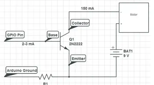
I have this basic circuit of how to drive a motor using a 2N2222 transistor and it all makes sense to me.
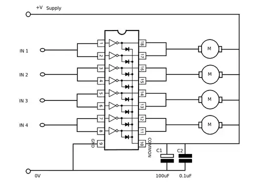
I found a bunch of cheap ULN2803APG darlington drivers. I am a bit confused on how to wire 4 motors to this. I think the common part is confusing me. If I try to follow the logic as on the circuit above it seems I might fry my MCU I/O by doing this?
The DC Motors need to run of 6Volts and draw a MAX of 200mA each at full load. I don't need speed control or anything like that really.I want to use this because its cheaper than getting L239 H-Bridge driver.(My counting is that I can get 25 of these vs 1~2 L239 for same price)
In my head I have it that I wire:
- MCU I/O pins to the
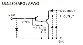
I1-I4Ranges (The "Base") Common"Emmiter" to GroundO1-O4"Collector" toMotor -Motor +to my Motor supply voltage- Motor supply voltage - to common ground?
Is this correct? I tried to follow it analogically as possible but I have a bad feeling about this?
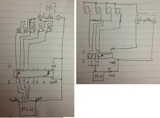
Left - My original thoughts
Right - As per comments m.Alin