5

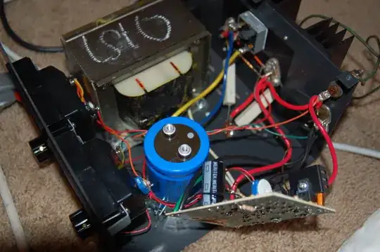
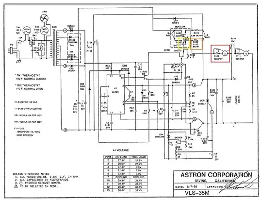
I just bought a 5-32 volt bench power supply with analog volt and amp displays yesterday. The device is an Astron VLS-10M. I just blew the supply while trying to charge a 150F capacitor with the current on full. I had a look inside, and I have no clue what could have gone wrong...

It has a 5 amp fuse, but the fuse did not blow. When I turn it on, the voltage reading will vary when I turn the knob, but the current is very limited. When I set the current to the highest setting, it will not even turn on a 24 volt horn which it turned on before. The Amperage meter will stay at zero, not moving on any load, only the voltage will go down, so it seems like the current limit is stuck at a very low value. The filter capacitor made a huge spark when shorting, in case that is relevant.

Does anybody have suggestions on steps to troubleshoot and repair the device?

So to recap, there is a voltage on the output, just the thing doesn't seem to want to supply very much current, dropping the voltage on most loads (except for small things like small bulbs etc.) There are two 2N3772 transistors on the back outside. Could this be a power transistor failure?

I also found an lm723 in it. Could this be broken?

I even called astron, and they just hung up on me!

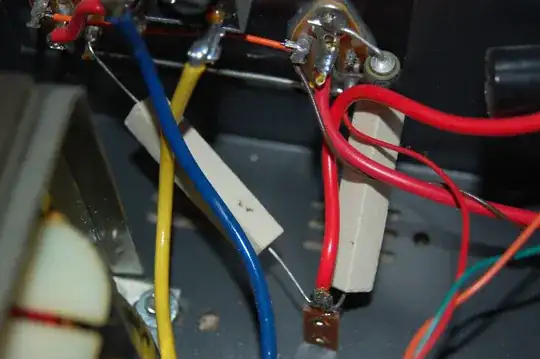
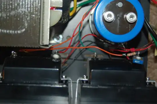
Here are some images:

enter image description here enter image description here enter image description here enter image description here

Passerby
  • 72,580
  • 7
  • 90
  • 202
skyler
  • 10,136
  • 27
  • 80
  • 130
  • 1
    Do you have a circuit diagram? Pictures? First hunch is to check current shunt and associated feedback circuit. – jippie Aug 19 '13 at 17:37
  • I cant find the schematic, but I added some pictures. – skyler Aug 19 '13 at 17:49
  • Are those big white resistors shunts? – skyler Aug 19 '13 at 17:53
  • 1
    try http://www.repeater-builder.com/astron/astron-index.html they have pdfs of circuit diagrams for various PSU - not yours but they all look surprisingly similar circuits. My guess is you blew the 2N3772 transistors and you're getting a voltage feedthrough base - emitter from the lm723 – JIm Dearden Aug 19 '13 at 18:14
  • Check the reference designs in the [datasheet](http://www.ti.com/lit/ds/symlink/lm723.pdf) and use it to interpret or draw the circuit of your power supply. Different datasheets may have different reference implementations. – jippie Aug 19 '13 at 19:03
  • Why does it look like the big blue cap is not connected? – jippie Aug 19 '13 at 19:04
  • Do you know how to check a regular BJT for shorts or opens? That is an important bit of knowledge in troubleshooting. – jippie Aug 19 '13 at 19:07
  • This thing almost looks like a homebrew bench power supply. Very interesting. *Makes an entry in the list of brands to avoid...* – JYelton Aug 19 '13 at 19:25
  • @jippie first, the cap gets screwed onto the board, OP probably unscrewed it to look under the board. Also, Astron has been making the same supplies for decades. Different variations on them. Finally, these get lots of modifications, so someone might have gone in before OP and changed stuff. – Passerby Aug 19 '13 at 19:31
  • Can I have some help in checking the BJTs for shorts/opens? It seems like they are open because it seems like they are open for it seems like all the source of power is coming from the lm723. – skyler Aug 20 '13 at 01:13
  • I'm nowhere near being a professional in analog design, but this PSU looks like it was assembled by a 12 years old. I won't be surprised if you could rip half of the components off their places just by shaking this piece of s*** – Vasiliy Aug 20 '13 at 11:32
  • I didn't have time yet to review the answers, but check this question: http://electronics.stackexchange.com/questions/79518/how-do-i-check-a-bjt-transistor-if-it-is-still-functional – jippie Aug 20 '13 at 19:36

3 Answers3

3

Based on your comments to hex4def6's answer, I understand the following:

  • The voltage adjustment works fine (verified with an external voltmeter)
  • The voltage indicators are fine (verified with an external voltmeter)
  • The supply can drive output current (verified with an external ampermeter + the load resistor gets hot)
  • The current indicator is broken (it shows zero current even when an external ampermeter measures non-zero current)
  • The current capability reduced

Are these statements correct?

If they are:

It seems like the supply itself is generally Ok, but its current indicator is broken + some reduction in current capability.

In order to indicate the possible root-causes of the issue we need to see a complete schematics. I didn't find your VLS-10M on the web, but I found VLS-35M:

enter image description here

These two are probably the same architecture, just having different number of paralleled pass transistors for driving the current (this one has 8 and delivers 35A intermittent current , while yours should be 2-3 which accounts for 10A).

If it is really the case that internal ampermeter is broken, I see three places where this could happen, without ruining the whole PSU:

RED: The pot used for current scale adjustment or the analog scale itself can be broken

ORANGE: The negative feedback (stabilizing) power resistor which is also used as a shunt for internal ampermeter can be broken

YELLOW: The pass transistor which feeds the above shunt resistor can be broken

Both orange and yellow failures would result in reducing the current capability of your PSU. If the current capability of your PSU is the same as before, I'd say that the issue is either the pot or the analog scale. However, based on your description, it looks like there is some reduction in current capability.

In order to verify this probe the voltage on the shunt resistor - if the voltage changes when you change the output current (by attaching smaller load for example) then both the resistor and the transistor are (probably) fine.

BTW, how comes PSU which is rated for 8A continuous current has 5A fuse?

Hope this helps.

Vasiliy
  • 7,323
  • 2
  • 21
  • 38
  • Yeah I think that the yellow is the failure. I popped out the 2 transistors, and one was failed open. – skyler Aug 20 '13 at 13:19
  • @skyler, try to solder the working transistor in the place of the one which is broken. If the current meter is back to life - just buy another transistor. However, if the current meter won't work, the problem may be more complex than that. – Vasiliy Aug 20 '13 at 13:58
  • Ok. I removed the broken transistor and replaced with working. The volt meter seemed to be working, and I set it up to 12. I then placed a small car inverter for a test load with a small 120v fan, and the ampmeter went up to 5 amps. So now all I have to do is replace transistor and then im good? – skyler Aug 20 '13 at 15:44
  • The only problem is that the amp meter was not accurate. When I was drawing 1 amp as read on an external ampmeter, the meter said 5. Will this be fixed by adding in the other transistor, or adjusting the POTs? – skyler Aug 20 '13 at 15:48
  • There is a 1 k pot that is on the second picture, which I may have turned a bit, could that be the inacurate amp meter problem source? – skyler Aug 20 '13 at 15:50
  • @skyler, I believe that once you replace the broken transistor your PSU will be back to what it was before. When you are not at current's limit, the current which was once supplied by two transistors is now flowing through a single one. This should make the current meter of the PSU (calibrated for 2 transistors) to show x2 current than is flowing into the load. I don't know where this factor of x5 comes from. I suggest you'll replace the transistor, and if there will be additional problems - post another specific question. – Vasiliy Aug 20 '13 at 16:05
  • ok. I will order a few new transistors – skyler Aug 20 '13 at 17:27
0

I have built almost same fully by myself, and made one mistake during build which caused small driving transistor to short emitter and collector all the time. Lost total of 3 till I did not find that by mistake I placed resistors of wrong value , used 680 ohm instead 68 ohm. After that it started working but only voltage regulation, no current. Than found that pin 10 was not connected and it go direct to middle pin of 500ohm potentiometer which is used for current limiting. After fixed that everything started working. So if u do not have shematic , and voltage regulatiion working as it should and looks stable under load, than in ur case current limiting is connected usually around pin 2 on LM723. So go like this:

Is voltage regulation working (use external voltmeter ) if no replace lm723 and before replace check voltage on pin 12 it should not exceed 37 volts. As well if voltage regulation does not working, and change of lm723 does not fix thing, than if there is no voltage on output or it is very low, main power transistors are broken or transistor which driving big ones is broken, but if voltage not working and u getting max voltage at output, than it either power transistors or driving one are shorted between collector and emitter.

If current not working but voltage do work and u can take full power without regulation than middle output on current regulation is not connected to IC or some of resistors which are connected to sides of current potentiometer not working. At the end if everything looks ok but current limiting not working, than reason again is LM723 itself.

I know I answering 5 years later but better ever than never xD .

0

It doesn't look like there's a whole lot going on in that design. First I'd look for smoky bits; any resistors look charred?

You could desolder the transistors and check to see that they're operating correctly. Luckily they socketed the LM723, so it'd be easy to test / replace that as well.

If you set the voltage, under no load, does the voltage at the output appear to be correct? If you have a small load (say, 1kohm), does the voltage droop?

Is it possible you charged up the cap, and then connected it the other way around to the power supply?

EDIT: Found a really nice annotated schematic of another Astron PSU: http://www.repeater-builder.com/astron/pdf/astron-rs35m-annotated.pdf

Looks like it's really similar in design.

If I were you, I'd do a digikey run for those three components (buy some spares as well).

hex4def6
  • 213
  • 1
  • 7
  • I did find a broken ceramic capacitor that was connected in series with a 2200 µf elecdrolidic on the output. As far as charred components, I didn't find much. It may have been possible that I charged it and connected it backwards, but I don't think I did, but possibly. As far as digikey 3 components, get 2 transistors, and lm723? – skyler Aug 19 '13 at 18:26
  • The voltage does not drop with a 1 k resistor and the resistor gets hot. The amp meter does not increase even when it hit about 1 or so amps on my external amp meter before the volt meter drooped – skyler Aug 20 '13 at 00:36