EDITED. I found that my supply of 3V was insufficient as there are voltage drops across the transistors. I replaced the 3V supply with 4.5V and the motor ran fine - although now my 3V motor has 2.5V across its terminals (3.3V to 0.8V). I did not think that DC motors exhibited any voltage drop since the current through their coils is constant. What can be done about this? And how would you calculate the voltage fed to the motor ANYWAY? I found it to be 3.3V simply because I measured it.
I have read over the data sheet for the L298 and it seems quite simple to use. Using one side of the chip (i.e. one H-Bridge) set IN1 to 5V and IN2 to ground to conduct from OUT1 to OUT2. Also, to enable the H-Bridge ENA must be 5V. That is all the wiring needed aside from some stabilizing/filter capacitors and flyback diodes.
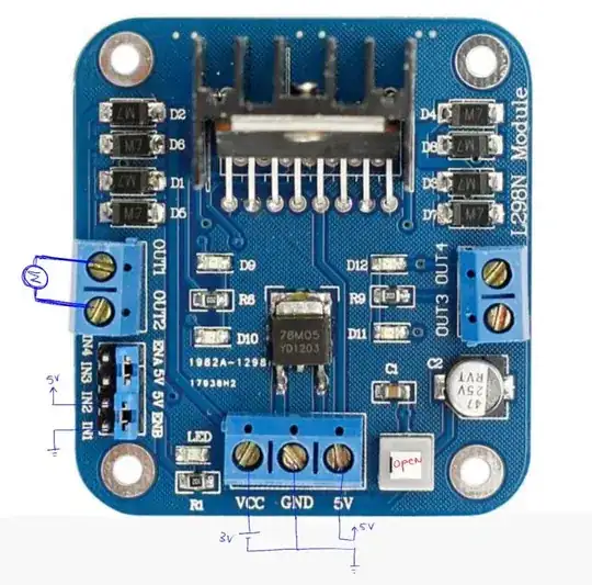
So, to not mess with all of that I have simply purchased the Sainsmart L298 Driver module. Below is a photograph of the module and I have drawn on it to illustrate the pins that I have wired.
*Note that I have not included the 5V to ENA because (shown towards the bottom left) the board has some jumpers connected so the pin is always 5V.
Also, there is a state switch at the bottom right. From my experiments, and from what I have read, if the button is depressed (closed) then then VCC is tapped and regulated at 5V for the logic circuitry and the 5V (far right of the bottom screw assembly) can be used to power external circuits. If the button is OPEN then VCC is not regulated and you must supply an external 5V supply to this pin for the logic.
Now, my motor is only rated MAX at 3V DC, so obviously I have to leave the switch open and supply the two sources independently.
What I have noticed:
If I have everything wired up exactly as I have shown in the depiction below (but without the motor!) it works fine!
I have put a multimeter across OUT1 or OUT2 to ground as my microcontroller code executes (simply code to run one way then reverse direction), the polarity of the pin changes as expected.
If I place my motor across a 3V supply momentarily - it runs!
If I place the motor leads into OUT1 and OUT2 (after I have verified that the voltage polarity switches) nothing happens. Actually, the indicator LEDs that show direction (that were working prior) no longer light up with the the polarity of IN1 and IN2 changes.
What the heck is happening? Could it be that the board is not supplying the current required to turn the motors? These motors are quite small and the Absolute Max current draw of the L298 is 2A for a single bridge. I checked the datasheet for these motors and they draw 2.2A at stall and 300mA no load.
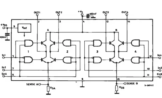
Here is the schematic for the actual L298 pin soldered to the above board. As you can see, the wiring scheme that I provided above should work just find. OUT1 should conduct to OUT2. The board just includes protection diodes and filter capacitors.