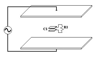
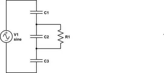
Let's assume for the purpose of theoretical discussion that your outer capacitor consists of two parallel plates connected trough a voltage source, and the inner capacitor consists of two parallel plates connected through resistor (it is what shown in your diagram, but said aloud).
DC analysis:
First we need to understand what happens in DC conditions.
Imagine that the outer capacitor is charged to some voltage and the inner capacitor have zero voltage across the load resistor when inserted in between the plates of the outer one. Now we want to know what happens to the inner capacitor when the system gets to its steady state?
It is clear that the current trough the load resistor must be zero (otherwise no conservation of charge). This means that there is no potential difference between the plates of the inner capacitor. This, in turn, implies that there is no electric field inside the inner capacitor. Does this mean that there is no charge on its plates? The answer is NO - there is charge transfer takes place through the load resistance and the transferred charge accumulates on the plates and neutralizes the external electric field.
From this DC analysis we see that there is charge transfer between the plates of the inner capacitor and the induced current through the load resistor.
AC analysis:
From the above discussion we know that there is induced current once the induced charge on the inner capacitor is not neutralizing the external electric field. This means that if the external field would oscillate, so will the charge on the inner capacitor. This gives rise to an oscillating current through the load resistor.
It is clear that the magnitude of the induced current will be proportional to the magnitude of oscillating electric field.
It is also clear that it will be proportional to inner capacitor's area (neglecting the fringing of the electric field), the separation between the plates and the dielectric constant between the plates. These three are equivalent to saying that the induced current will be proportional to inner capacitor's capacitance. Note: this is true while the inner capacitor is physically smaller than the external one.
Note that due to the load resistance, the charge transfer is not instant, but follows the usual capacitor's characteristic, having a time constant of RC. This means that there is intrinsic low pass behavior to this system.
Conclusion:
You are correct - this setup can be employed for transferring energy.
Why isn't it used? Well, I can only speculate here. My guesses are:
- Assuming that dielectrics are the same for both outer and inner capacitors, this setup may be used for reducing the voltage only.
- The intrinsic low pass behavior may be not desirable.
- The control over capacitors' areas is more complicated than the control over number of windings in inductors.
- It is very easy to ensure that almost 100% of primary's magnetic field passes through secondary windings. It is more complicated with capacitors and the electric field.
- In order to increase efficiency and reduce physical size you want the capacitors to be thin (small gap between plates), but this results in lower breakdown voltage.
And I'm sure that there are more reasons. Also I'm completely sure that there are some specialized applications where this technique is employed.