6

I have a problem with SPI communication with ENC28J60 chip. Basically I can't use SSP in SPI mode as it is, because ENC28J60 expects CS to be low for multiple bytes while SSP shifts it high after each byte transmitted. To overcome this, I have GPIO bit acts as CS. Looking at logic analyzer signal, it seems correct to me, but still I don't get the expected result.

I have connected LPC1788 <-> ENC28J60 like this:

SSP0_SCK  - SCK
SSP0_SSEL - NC
P0_19     - CS
SSP0_MISO - SDO
SSP0_MOSI - SDI
GND       - GND

Signal looks like this: LA output

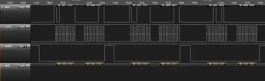
MOSI looks correct, clock is somehow strange (I'm not sure if this 0.5 us delay is normal), enable is also correct, but MISO should return something on last MOSI byte (0x00).

EDIT: I have changed the clock to be compliant with ENC28J60 (clock low at idle). Picture is updated as well.

abdullah kahraman
  • 5,930
  • 7
  • 59
  • 104
Gossamer
  • 663
  • 6
  • 14
  • The clock looks odd but I wonder if it's measurement error, does the analyzer have an option to increase the sampling rate? – PeterJ Aug 16 '13 at 08:37
  • Yes it does, but even on 24MhZ and 100MSamples i get similar output. SPI is set at 5MhZ – Gossamer Aug 16 '13 at 08:54

2 Answers2

3

It works now. Master output was connected to SDI. That seemed logical to me. For some reason SDO <-> MOSI did the trick. So either board connectors are wrongly marked or ?

Gossamer
  • 663
  • 6
  • 14
2

The 0.5µs delay is pretty normal. A lot of SPI interfaces squirt data in 8 groups of 8 bits.

I had a look at the datasheet for the ENC28J60 here, on page 25, it states that:

the SPI port requires that SCK be at Idle in a low state;

It would appear to me as if your clock is in the correct SPI mode (Mode 0), it is idle HIGH.

I cannot explain why this would affect communications, but I can only imagine it doesn't help.

ps What commands are you trying to send?

Mitchell
  • 81
  • 1
  • 7