81

I've always wondered this: every single modern PCB is routed at 45 degree angle increments. Why does the industry prefer this so much? Doesn't any-angle routing offer more flexibility?

One plausible theory would be that the existing tools only support 45 degree increments and that there isn't much pressure to move away from this.

But having just researched this topic on google, I stumbled across TopoR - Topological Router - which does away with the 45 degree increments, and according to their marketing materials it does a considerably better job than the 45-degree-limited competitors.

What gives? What would it take for you personally to start routing arbitrary angles? Is it all about support in your favourite software, or are there more fundamental reasons?

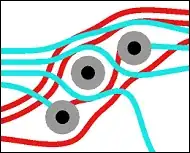
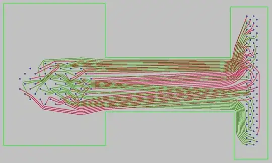
Example of non-45-degree routing: alt text

P.S. I also wondered the same about component placement, but it turns out that many pick & place machines are designed such that they can't place at arbitrary angles - which seems fair enough.

Roman Starkov
  • 2,731
  • 5
  • 25
  • 26
  • 12
    As a side note, when using 45 degree routing, octagonal vias will give you the greatest clearance while maintaining more copper area on the annular ring. – Kevin Vermeer Dec 16 '10 at 17:05
  • 2
    I'd also point out that the free gEDA PCB program has a toporouter - Not just this one. Does the same thing, and I don't think that it's due to its removal of the 45 degree limitation. – Kevin Vermeer Dec 16 '10 at 17:06
  • 2
    @reem never seen an octagonal via, and Google Images isn't being helpful... if you post a link I'll be grateful! Also thanks for mentioning gEDA, looks very promising. – Roman Starkov Dec 16 '10 at 19:36
  • Modern tools support arbitrary angles, so that's no longer the reason. – Brian Carlton Dec 17 '10 at 16:52
  • @rom - Eagle has octagonal vias and pads, and they're also available in gEDA. – Kevin Vermeer Dec 17 '10 at 20:42
  • @romkyns - Octagonal pads are a option in Altium as well. – Connor Wolf Dec 21 '10 at 07:16
  • @romkyns, The given example is the result of an [autorouter](http://www.eremex.com/products/topor/competitiveadvantages/autorouting.html), not manual routing. Many of the answers given apply only to manual routing (re: design efficiency). – tyblu Jan 16 '11 at 00:35
  • @tyblu I know. I still don't see any logic in claims that manual routing on the grid can be better quality than manual routing without a grid. – Roman Starkov Jan 16 '11 at 00:38
  • @romkyns, It's really just design time & effort -- you don't have to *tweak* tracks when routing on a grid, because you know they're following the minimum spacing you setup beforehand. When going for minimum spacing without a grid you have to check spacing, or rely on a real-time DRC to tell you that you screwed up. – tyblu Jan 16 '11 at 00:42
  • 2
    @tyblu with crappy tools - maybe. I don't see why a good tool wouldn't let your tracks "snap" to minimum spacing you've set in your design rules. Seriously, I understand the argument that current tools suck at that, but not that this is an inherent property of no-grid design. – Roman Starkov Jan 16 '11 at 02:26
  • 8
    "Liquid PCB" https://sourceforge.net/projects/liquidpcb/ makes some interesting-looking traces with lots of graceful curves. – davidcary Feb 05 '11 at 15:31
  • 3
    Modern tools support arbitrary angles, so that's no longer the reason. – Brian Carlton Dec 16 '10 at 00:46
  • I know this discussion took place a while ago, however I'd like to invite you all to the English speaking forum related to TopoR. If you have any questions regarding this tool, feel free to ask them there :) http://forum.eremex.com/ – Elena Fulton Aug 11 '11 at 07:56
  • Noone remembers acid traps? – Scott Seidman Mar 06 '13 at 13:30
  • 1
    @ScottSeidman Clearly not, would you like to expand? Sounds interesting. – Roman Starkov Mar 06 '13 at 13:44
  • With acid etching techniques, acute angles would cause acid to pool in corners, doing bad things. Of course, 45 degree angles don't mean you can't have acid traps: http://www.innofour.com/image/picture/INNOFOUR04171_web.jpg – Scott Seidman Mar 06 '13 at 13:54
  • Perhaps it partially boils down to looks. The above picture looks sort of like 3rd grade drawing. – Erik Friesen Jul 03 '14 at 12:04
  • The TopoR link in the OP's question is dead. – gbmhunter Apr 27 '16 at 04:38

11 Answers11

36

Fundamentally, it basically boils down to the fact that the software is way easier to design with only 45° angles.

Modern autorouters are getting better, but most of the PCB tools available have roots that go back to the DOS days, and therefore there is an enormous amount of legacy pressure to not completely redesign the PCB layout interface.

Furthermore, many modern EDA packages let you "push" groups of traces, with the autorouter stepping in to allow one trace to force other traces to move, even during manual routing. This is also much harder to implement when you aren't confined to rigid 45­° angles.

Connor Wolf
  • 31,938
  • 6
  • 77
  • 137
  • 3
    Accepted. For the record, TopoR claims to be able to push groups of traces better than standard tools do - although I haven't tried myself. I take your point that it's harder to program arbitrary angle autorouters, but people have done much harder things... there just isn't enough demand for this somehow (and I still don't know why :D). – Roman Starkov Dec 19 '10 at 00:20
  • 2
    Also, I've tried the TopoR demo, and it feels *very* "alpha" to me. The interface is very clumsy. – Connor Wolf Dec 19 '10 at 04:54
  • 3
    As for why there isn't much demand? The EDA software market is *tiny* is why. – Connor Wolf Dec 21 '10 at 07:17
  • Straight line segments are way easier to calculate without loss of precision compared to arc line segments. This used to be a problem in the early days, when processing was limited, but now it is not. Everyone just keeps using 45 degree angles because everyone uses 45 degree angles. – Jeroen3 Jun 15 '17 at 06:58
23

See https://sourceforge.net/projects/liquidpcb/

It's an EDA CAD package I was writing, but developement slowed a lot when I had kids. It does not support straight tracks at all. All tracks are freely curving and take the most optimal routes to their destinations.

LiquidPCB

Daniel Grillo
  • 7,659
  • 18
  • 51
  • 69
Rocketmagnet
  • 26,933
  • 17
  • 92
  • 177
16

I don't think there exists such a strong preference for 45 degree angle. I have seen an old Tektronix Oscilloscope (Tek 2213 to be precise) board with traces that looks like hand drawn :-)

enter image description here

C--
  • 691
  • 4
  • 9
  • 18
  • 31
    The reason the traces look hand-drawn is because they are. The 45° preference thing is only common on *computer designed* circuitboards. Your tek scope predates computer PCB design, and as such the layout was indeed done manually (with tape, to be specific). – Connor Wolf Jul 30 '13 at 17:56
  • 3
    @ConnorWolf: And we still complain about our PCB tools ;) Designing something like that without CAD is pretty impressive. – Rev Aug 03 '16 at 13:35
16

It looks more tidy, and enables the most tracks to be put into a given area. it's also better for controlled impedance tracks.

Leon Heller
  • 38,774
  • 2
  • 60
  • 96
  • 8
    To add to this: as you do your routing on a fixed grid, parallel lines will be at least 1 gridmark away. If they make a corner together a 45° angle gives the most space between those two tracks on the diagonal. Different angles may require that these tracks start farther apart to ensure minimum spacing, resulting in less dense routing than optimal. [Note that I'm not saying that more dense is better, but often desirable.] – tyblu Dec 16 '10 at 00:15
  • 2
    I said "a 45° angle gives the most..." and should have said "a 45° angle gives more... than if the angle were less." – tyblu Dec 16 '10 at 01:14
  • 7
    @tyblu I'm sorry but this makes no sense whatsoever. Firstly, diagonal lines on gridmarks are NOT spaced 1 gridmark away but only 0.7 gridmarks away, and secondly, if you have more angles you ALWAYS have more opportunity for denser routing. How can you possibly have less chance to route densely by routing in a way that entirely contains 45 degree routing as a special case? – Roman Starkov Dec 16 '10 at 10:55
  • @romkyns, There are some misunderstandings. Following common design principles, you are limited to <45° corners, follow a fixed grid and an xy orientation. Achieving transitions from horiz. to vert. using <45° on a fixed grid uses more space than 45°. – tyblu Dec 16 '10 at 13:58
  • @tyblu Right, indeed, there was a misunderstanding on my part. Under those constraints a 45 degree joint makes sense, but those seem like very artificial constraints to me. I guess my question could then be rephrased to "why do PCB professionals still operate under these artificial constraints of x/y orientation and a fixed grid?" (I think I got my answer though: too much legacy software in this industry) – Roman Starkov Dec 16 '10 at 19:30
  • Fixed grid and xy-orientation: faster design time while ensuring spacing and alignment. <45°: [avoids acid](http://www.pwtpcbs.com/glossary/acidtrap.html) [traps](http://www.cadence.com/Community/forums/p/11497/15062.aspx); high-freq. considerations (500MHz+ sine or 50MHz+ digital). – tyblu Dec 16 '10 at 19:37
  • 1
    I still don't see how 45 degree routing enables "the most tracks to be put into a given area". Nor why it's better for controlled impedance tracks. @Leon, were you comparing to arbitrary angles or to 90 degree routing? – Roman Starkov Dec 21 '10 at 10:15
  • It's a packing space problem, not just a legacy problem. Imagine a box and a bunch of little sticks you're trying to pack in the box. If a human being does the packing, they're going to either go with everything at 90 degrees or they're going to just naively toss them all in. Which one do you think is going to work better? I doubt that autorouters are generally smart enough to not have the same problem, really. – darron Apr 25 '11 at 14:48
  • @darron: A human being might also go with 60-degree angles. Actually, board layout based upon an equilateral-triangular grid would probably work very nicely if component dimensions were designed to fit on such a grid, and if placement equipment could routinely handle 60-degree rotations. Hexagonal chip packages could have shorter leads near the corners than would rectangular or square ones. Efficiently cutting a wafer into hexagonal dice would require zig-zag cuts, however, which might be harder than using straight cuts across the wafer. – supercat Mar 06 '13 at 15:53
12

This predates any issues with PCB software and routing: The three main reasons we were given in electronic engineering classes in the late 1970s were:

1) The sharp outside corner of the bend can cause issues at higher frequencies as the points can act as mini antennas and radiate the signals

2) Because the outside corner of a 90 degree bend is a thin point it can be etched away easily if etching times are not very carefully controlled and so affect the thickness of the trace

3) The 90 degree inside and outside corners make that area more susceptible to problems where the etching process eats underneath the trace.

Linker3000
  • 1,289
  • 9
  • 11
  • 7
    I understand how 45 degrees is better than 90 degrees, but I meant to ask why it's still used in preference to arbitrary angles and curves. – Roman Starkov Dec 19 '10 at 00:18
11

Another thing to consider is that it makes Gerber files smaller. Gerber files define a series of lines (among other shapes).

e.g. To draw a true circle in a Gerber file takes hundreds (thousands?) of lines. But to draw an octagon takes only eight lines.

Eric Cox
  • 304
  • 1
  • 4
  • 6
    Why are smaller gerber files better than larger ones? – tyblu Dec 20 '10 at 18:18
  • Used to be an issue, not really one any more. – Connor Wolf Dec 21 '10 at 07:18
  • 4
    Another argument highlighting that the problem is ancient legacy software. @Fake, do you mean that Gerbers can now represent arcs efficiently, or that nobody cares if the design is a few tens of MB? – Roman Starkov Dec 21 '10 at 10:12
  • 11
    @tyblu, Many of the routing machines more than a year or two old still use 9600 baud serial lines. I wrote a utility that converted Gerber files into a format used in a Fuji pick-n-place that is still in use at my old company and several others. The machine's only link to the outside world was 9600 baud serial, on which sat an Irix-based PC with some proprietary software on it. I guess a 10MB Gerber is fine for you, until you're the one who has to sit and wait a half hour for it to load between designs. – Eric Cox Jan 07 '11 at 23:28
  • 6
    10MB/9.6kbps is about 2.5 hours; I see your point! ;) – tyblu Jan 08 '11 at 00:10
  • 4
    Of course this doesn't just affect the Gerbers. It also affects the design database. It takes less bits to represent a straight line between two points than an arbitrary curve. And a smaller design database is going to give a more responsive tool. You might not see the difference on a 2-layer board, but the guy designing a 16-layer PC motherboard will probably notice the difference. – The Photon Mar 06 '13 at 17:01
  • 1
    There aren't arc-primitives in gerber files? Really? That's terrible. We have them in gcode, and that's a similarly ancient description language. – Connor Wolf Jul 30 '13 at 17:57
  • 4
    There are arc-primitives in gerber files, but they are not used by every pcb cad system. It is possible to draw a true circle or arc without using hundreds of lines. Just read a gerber manual by UCAMCO. – Uwe Oct 21 '16 at 07:35
  • 2
    Gerber files support circles and arcs, this should not be a problem for tools using RS-247X. – Jeroen3 Jun 15 '17 at 07:04
  • 2
    Of course, it only makes the gerbers bigger if you use curves or lots of tiny line segments. A single gerber line is a plotter command containing "point a" and "point b" and it always the same size no matter what angle it goes at. :) Just worth noting. – tekHedd Jul 06 '19 at 22:27
9

For my own PCBs I like rounded & curved tracks, no problems there as long as you are routing manually.

In most of industrial PCBs it's just a tradition due to limitations on early/current routing software.

Less sharp angles = /*marginally */ better signal quality.

BarsMonster
  • 3,267
  • 4
  • 45
  • 79
  • 4
    The last time I bothered to look at my motherboard up close I think I noticed that all the traces were radiused at all corners – Nick T Dec 16 '10 at 02:16
  • 11
    i wouldn't say "marginally better signal quality". Radiused corners to the point of laser trimmed "rounding" may be mandatory for operation at high frequency. – Mark Dec 16 '10 at 02:40
8

The primary reason is that it makes for an easier problem set, and can be easier to design. There are some useful properties that a 45/90 degree system provides. The primary reason I'll say is that it lets you keep your desired grid spacing without a big penalty.

If you start from a point in a grid, each cardinal direction (up, right, down, left) will arrive at an adjacent grid point at 1 unit. Any 45 degree angle will also arrive at an adjacent point, although the distance will be (sqrt 2) units. If you were to use an angle such as 30 or 60 degrees, you would arrive at a midpoint between a grid point, which would require you to have a finer grid. A finer grid increases the computation time for path evaluation and may make it more difficult to cleanly optimize the circuit.

The TopoR software uses a completely different algorithm from the typical router, which makes it unique. The PCB designs that TopoR makes looks similar to old hand-drawn PCB layouts from the 60's-70's.

W5VO
  • 18,303
  • 7
  • 63
  • 94
  • 6
    But "grid spacing" is just begging the question, as the concept of a "grid" is just an artifact of XY design. – markrages Dec 17 '10 at 19:06
  • Hadn't thought of it that way. You're right – W5VO Dec 17 '10 at 19:44
  • 1
    Aligning things on a grid helps to avoid situations where when using e.g. 5 mil tracks with 5 mil spacing, there ends up being a 14 mil space on one side of a component where it would be useful to have a track, while on the other side there's a 7-mil space that could just as well be a 5-mil space. If one has tools that can efficiently move things around while keeping a layout tidy, one could simply shove the component and some tracks to expand the 14-mil gap to 15 mils, but if one can't move things so nicely, it's easier to start with a grid and avoid such problems in the first place. – supercat Apr 25 '11 at 16:20
1

I read that historically PCB production machines had only 90/45/0 movements, but most importantly, 45 degree is preferable to 90 degree curves because in the dol times 90 degree turns were prone to deterioration, so it was more likely that a 90 degree turn would lose copper and break the connection... so before software, hardware reason... it's all about history, and legacy

Francesco
  • 311
  • 1
  • 3
  • 10
1

The reason is that traditionally (from 60s) mask flashing machines were working with a limited set of blinders and flashes, as well as angles were fixed. Some were not capable of making precise rotation other than 45 deg. The same, software did not allow flash overlapping other than 90 and 45 deg, avoiding flashing wrong corners. Well, and it looks better, making it easier to track down problems.

Asdf
  • 121
  • 3
0

No one said it before, so here is a little explanation: When a PCB trace turns a corner at a 90 degree angle, a reflection can occur. This is primarily due to the change of width of the trace. At the apex of the turn, the trace width is increased to 1.414 times its width. This upsets the transmission line characteristics, especially the distributed capacitance and self–inductance of the trace — resulting in the reflection. It is a given that not all PCB traces can be straight, and so they will have to turn corners. Turns at 45 degrees offer much better characteristics. The best characteristic you can obtain with rounded turns. You can find such tracks in RF applications.

  • Nothing wrong with what you said, but you do know that the added capacitance of a square corner can be safely ignored even for 10 ps rise time signals??? – SteveSh Dec 29 '21 at 16:10
  • The question is why not go all the way and smooth the corner into a nice, round arch. – Roman Starkov Dec 29 '21 at 16:47