9

I've got an RF transceiver (Nordic's nRF24L01+) which shows a typical circuit to match its antenna output to a single ended 50 ohm impedance.alt text

I've also got a chip antenna which comes with an example circuit to match a 50 ohm line to the antenna feed point.alt text

If I am going to place the transciever and the chip antenna very close, then there is no need for a 50 ohm transmission line right? If so, can I somehow merge those two matching circuits into one and thus reducing component count?

Toby Jaffey
  • 28,796
  • 19
  • 96
  • 150
cksa361
  • 3,814
  • 7
  • 33
  • 49
  • I have an answer, but not the time to place it. short answer, yes, you can combine them, but it is not as easy as not matching to an intermediate impedance. Can you place a link to your chip antenna for me? – Kortuk Dec 15 '10 at 00:16
  • This antenna --> http://www.antenova.com/?id=742, but the datasheet does not specify the nominal matching circuit, I had to email Antenova to obtain the above matching circuit on their reference board. – cksa361 Dec 15 '10 at 00:56

3 Answers3

10

I'll take a shot at this one as I'll be doing the exact same exercise for my work soon.

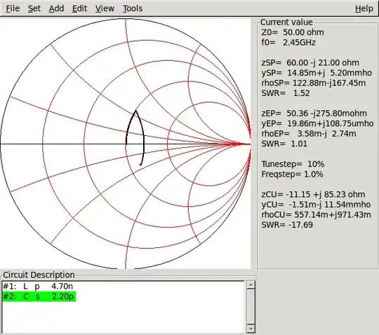
So the antenna impedance appears to be 60-j21 ohms:

alt text

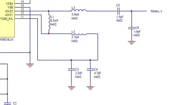
And the impedance looking out into L3 is 31-j7 ohms:

alt text

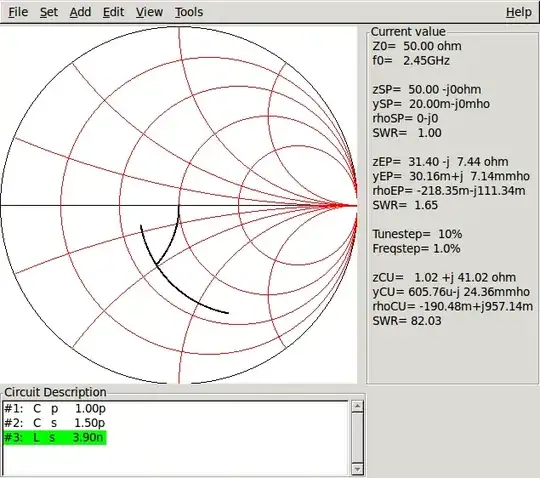
(This would imply a source impedance of 31+j7 ohms).

So how can we get from 60-j21 to 31-j7 ohms? A two-element matching network can do it.

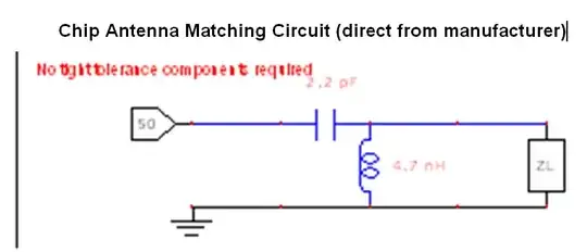
All that's necessary to make a match is two components. Here are a couple possibilities:

alt text

alt text

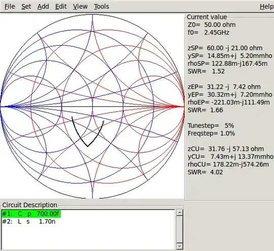
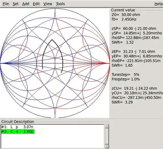
So the two two-component possibilities are high-pass (series L, parallel C) or low-pass (series C, parallel L). If the matching network is used as a filter for harmonic suppression, then the low-pass form is preferred.

On the other hand, the 24L01 outputs have a DC level at the power supply voltage. If you don't want DC on your antenna, a topology with a series capacitor for DC blocking may be desirable.

If the matching network is being used for filtering, it is desirable to be able to set the Q of this filter to get a steeper shape factor. Two topologies for this are the "PI match" and the "Tee match." Essentially they are two back to back two-element networks, matching to an intermediate impedance to set the desired Q.

(to be continued)

markrages
  • 19,905
  • 7
  • 59
  • 96
  • Thanks for your answer! The datasheet of the transciever specifies the source impedance to be 15+j88 ohms. So does that mean this source impedance (balanced) gets transformed to 31+j7 ohms by the time it gets through the balun and past L3? – cksa361 Jan 07 '11 at 00:40
  • What software is that? – Connor Wolf Jan 07 '11 at 01:39
  • @cksa361, yes, I think that's correct. Remember, there are a lot of limitations to this kind of analysis. The schematic doesn't show all the stray capacitance and inductance, so that doesn't make it into the analysis. – markrages Jan 07 '11 at 04:51
  • @Fake Name, the software is gsmc. http://www.qsl.net/ik5nax/ or "apt-get install gsmc" – markrages Jan 07 '11 at 04:52
  • Do you know why Nordic placed a DC level at their antenna? – mFeinstein Sep 13 '19 at 10:19
1

Yes, you can, but you probably don't want to. There are second order effects of the components that you have to be aware of. For example ESR (Equivalent Series Resistance) in caps. These caps are small and cheap, so I would look to save area/components elsewhere.

Brian Carlton
  • 13,252
  • 5
  • 43
  • 64
0

You should be able to do that. On the Antenna side, looking into that 2.2pF cap you should see 50 Ohm. On the transmitter side, you should see 50 Ohms looking in to the node between C5 and C6. Now, this might be a little narrow band, and require some tweaking, but you should be fine. I'd do some tweaking at the antenna range to make sure you got the range you really wanted, though.

rfdave
  • 1,821
  • 10
  • 7
  • 2
    I think he wants to remove some of the network, I do not think he is asking if the current circuit works. – Kortuk Dec 15 '10 at 02:47